66kV Transmission Tower: Complete Specifications, Types & Buyer Guide
2025-12-25
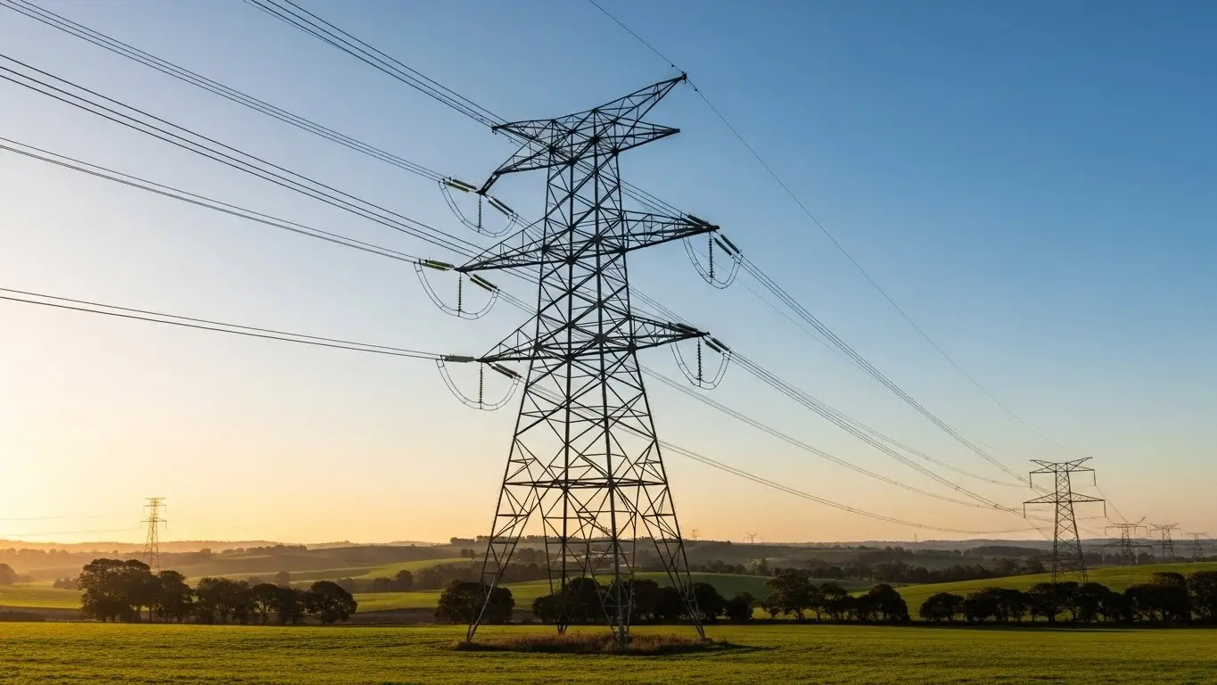
A 66kV transmission tower is a steel lattice or monopole structure that supports high-voltage power lines carrying 66,000 volts. These medium-voltage towers typically stand 15-55 meters tall, span 300-450 meters apart, and are constructed from Q345B galvanized steel with a design life of 50+ years.
| Specification | 66kV Tower Standard |
|---|---|
| Height Range | 15-55 meters |
| Tower Weight | 1,000-5,000 kg |
| Ground Clearance | ≥6.1 meters |
| Span Length | 300-450 meters |
| Steel Grade | Q345B / ASTM A572 GR50 |
| Galvanization | ≥86μm (610 g/m²) |
| Design Life | 50 years |
| Insulators | 6 disc per string |
If you're sourcing 66kV towers for a utility project, industrial power grid, or renewable energy transmission line, this guide covers everything you need to evaluate suppliers and make informed procurement decisions.
What Makes 66kV Different from Other Voltage Classes?
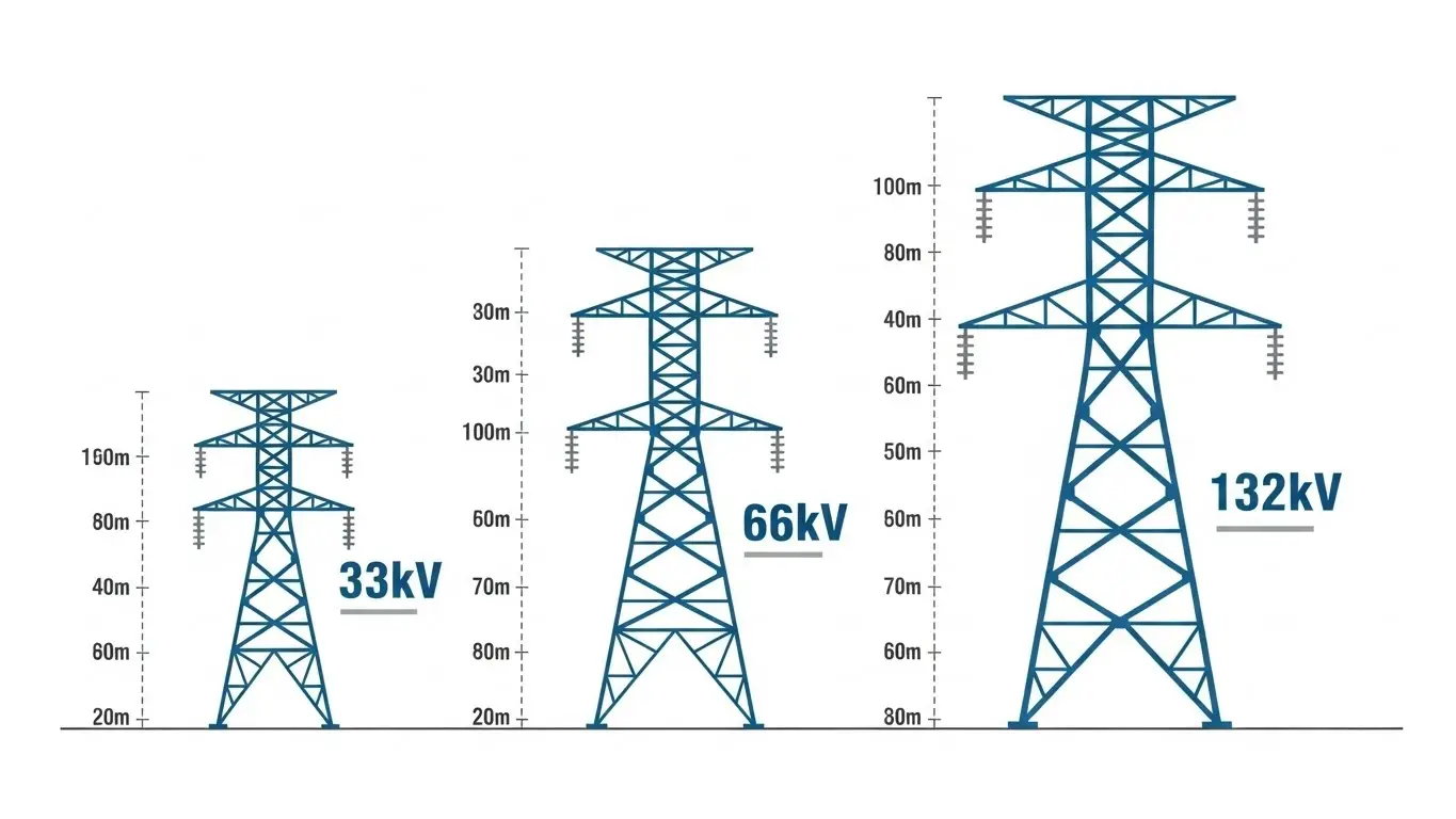
The 66kV voltage class sits in the sub-transmission category—bridging the gap between high-voltage transmission (132kV and above) and distribution networks (33kV and below).
Here's how 66kV compares to adjacent voltage classes:
| Parameter | 33kV Tower | 66kV Tower | 132kV Tower |
|---|---|---|---|
| Typical Height | 12-25m | 15-55m | 25-65m |
| Span Distance | 150-250m | 300-450m | 350-500m |
| Insulators per String | 3 discs | 6 discs | 9-10 discs |
| Tower Weight | 800-2,000kg | 1,000-5,000kg | 3,000-10,000kg |
| Steel Requirement | Q235B | Q345B | Q345B/Q420B |
| Ground Clearance | ≥5.5m | ≥6.1m | ≥6.7m |
The 66kV class remains widely used across Asia, Africa, and parts of South America because it offers an economical balance between transmission capacity and infrastructure cost. With 17 years of manufacturing experience, our engineering team at X.Y. Tower has designed 66kV structures for projects across 20+ countries where this voltage class remains the backbone of regional power distribution.
Types of 66kV Transmission Towers
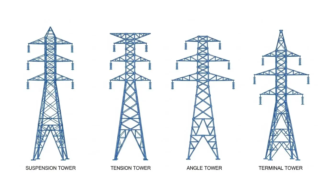
Not all 66kV towers serve the same function. The tower type depends on where it sits along the transmission line and what mechanical loads it must handle.
Suspension Towers (Tangent/Intermediate)
Suspension towers carry conductors on straight-line sections where the line runs in a single direction. They're the most common type on any transmission line—typically making up 80-85% of all towers.
Key characteristics:
- Supports conductors through suspension clamps
- Handles vertical loads from conductor and ice weight
- Lowest cost per tower
- Fastest installation time
Tension Towers (Strain Towers)
Tension towers handle the mechanical stress at points where the line changes direction or where conductors terminate. They use strain insulators instead of suspension types, anchoring the conductor rather than simply supporting it.
When you need tension towers:
- Line direction changes exceeding 2°
- Long span crossings (rivers, valleys)
- Before and after substation entry points
- Every 3-5km as dead-end sections
Angle Towers
Angle towers accommodate horizontal deviations in line direction. They're classified by the angle they can handle:
| Angle Category | Deviation Range | Typical Application |
|---|---|---|
| Light Angle | 0-15° | Minor route adjustments |
| Medium Angle | 15-30° | Moderate direction changes |
| Heavy Angle | 30-60° | Major route corners |
| Dead-End | 60-90° | Right-angle turns, terminations |
Terminal Towers
Terminal towers connect overhead lines to substations or cable transitions. They're built to handle unbalanced longitudinal loads since conductors only extend in one direction.
Transposition Towers
On lines longer than 100km, transposition towers rearrange conductor positions to balance electrical characteristics across all three phases. These are specialized structures that appear every 30-50km on longer routes.
Complete Technical Specifications for 66kV Towers
Structural Steel Requirements
The structural integrity of any 66kV tower depends on steel grade selection. Here's what international standards specify:
| Component | Steel Grade | International Equivalent | Yield Strength |
|---|---|---|---|
| Tower Legs | Q345B | ASTM A572 GR50 / S355JR | ≥345 MPa |
| Bracings | Q235B | ASTM A36 / S235JR | ≥235 MPa |
| Heavy-Duty Members | Q420B | ASTM A572 GR65 | ≥420 MPa |
Per GB/T 1591-2018 and ASTM A572 standards, tower leg members must achieve minimum yield strength of 345 MPa. Our production facility runs chemical composition testing and mechanical tensile tests on every steel batch before fabrication begins.
Galvanization Standards
Hot-dip galvanization protects steel towers from corrosion over their 50-year design life. The coating thickness directly affects longevity:
| Environment | Minimum Zinc Coating | ASTM A123 Class |
|---|---|---|
| Normal (rural) | 86μm (610 g/m²) | Grade 65 |
| Industrial | 100μm (700 g/m²) | Grade 85 |
| Coastal/Marine | 140μm (1000 g/m²) | Grade 100 |
With our own HDG factory in Guanghan, we control coating thickness and surface finish at every stage. This vertical integration means faster turnaround and consistent quality across orders of any size.
Electrical Clearance Requirements
Per IEC 60826 and national grid codes, 66kV towers must maintain these minimum clearances:
| Clearance Type | Minimum Distance |
|---|---|
| Ground (normal terrain) | 6.1 meters |
| Ground (cultivated land) | 7.0 meters |
| Road crossings | 7.5 meters |
| Railway crossings | 8.5 meters |
| Building proximity | 4.0 meters horizontal |
| Phase-to-phase | 1.2 meters minimum |
Insulator Configuration
66kV transmission lines use disc-type suspension insulators rated at 11kV per disc. A standard string requires 6 discs for normal conditions.
| Pollution Level | Creepage Distance | Disc Count |
|---|---|---|
| Light | 16mm/kV | 5-6 discs |
| Medium | 20mm/kV | 6-7 discs |
| Heavy | 25mm/kV | 7-8 discs |
| Very Heavy | 31-45mm/kV | 8-10 discs |
Design Standards and Certifications
When evaluating 66kV tower suppliers, verify compliance with these standards:
International Design Standards
| Standard | Application |
|---|---|
| IEC 60826 | Loading and strength design |
| ASCE 74 | Guidelines for transmission structures |
| GB 50545-2010 | Chinese technical code for transmission lines |
| DL/T 5154-2012 | Technical specifications for transmission tower design |
| EN 50341 | European overhead line design requirements |
Manufacturing Standards
| Standard | Requirement |
|---|---|
| ISO 9001:2015 | Quality management system |
| GB/T 2694-2018 | Transmission line steel tower fabrication |
| ASTM A123 / ISO 1461 | Hot-dip galvanizing |
| AWS D1.1 | Welding code for structural steel |
| ASTM A394 / ISO 898 | High-strength bolts |
At X.Y. Tower, our quality management covers ISO 9001:2015, ISO 14001 (environmental), and OHSAS 18001 (safety). Every tower batch undergoes full-scale prototype testing per IEC 60652 before production release.
Lattice Tower vs. Monopole: Which Structure for 66kV?
For 66kV applications, lattice towers dominate—but monopole structures have specific advantages in certain situations.
| Factor | Lattice Tower | Monopole |
|---|---|---|
| Cost per tower | $3,000-8,000 | $5,000-15,000 |
| Weight | 1,000-5,000 kg | 2,000-6,000 kg |
| Foundation size | Larger (4 legs) | Smaller (single base) |
| Right-of-way width | 15-25 meters | 5-10 meters |
| Installation time | 3-5 days | 1-2 days |
| Visual impact | Higher | Lower |
| Best application | Rural, open terrain | Urban, restricted corridors |
Choose lattice towers when: Cost efficiency matters, terrain is open, and visual impact isn't a primary concern.
Choose monopoles when: Right-of-way is restricted, urban aesthetics matter, or faster installation justifies higher unit cost.
Foundation Requirements by Soil Type
The foundation design significantly affects total project cost. Here's what your geotechnical conditions require:
| Soil Type | Foundation Type | Typical Depth | Concrete Grade |
|---|---|---|---|
| Normal soil | Pad/spread footing | 2.0-3.5m | M20-M25 |
| Soft soil | Raft foundation | 1.5-2.5m | M25-M30 |
| Rock | Rock anchor | 1.0-2.0m | M25 |
| Waterlogged | Pile foundation | 6-15m | M30-M35 |
| Sandy/loose | Drilled shaft | 4-8m | M25-M30 |
Foundation costs typically represent 15-25% of total tower installation cost. Accurate soil investigation before design prevents expensive modifications during construction.
What Affects 66kV Tower Pricing?
The cost per ton for 66kV towers ranges from $800-1,400 depending on several factors:
Steel market prices: Raw material represents 60-70% of tower cost. Q345B steel fluctuates with global commodity markets.
Design complexity: Angle towers and terminal towers cost 30-50% more than standard suspension towers due to heavier members and specialized hardware.
Galvanization specification: Coastal projects requiring 140μm coating add 15-20% to galvanizing costs versus standard 86μm.
Order volume: Orders above 500 tons typically achieve 8-12% better pricing through production efficiency.
Delivery terms: FOB vs. CIF pricing, inland transport distance, and port handling all affect final landed cost.
With 40,000 tons annual production capacity, we maintain competitive pricing while meeting delivery schedules for projects ranging from 50 to 5,000+ tons.
Procurement Checklist for 66kV Transmission Towers
Before issuing an RFQ, gather these specifications:
Project Information Needed
- Voltage class and circuit configuration (single/double)
- Total line length and estimated tower count
- Terrain profile (flat, hilly, mountainous)
- Environmental conditions (wind zone, ice loading, pollution level)
- Applicable national standards
Supplier Qualification Requirements
- ISO 9001:2015 quality certification
- Type test certificates per IEC 60652
- Reference projects with similar specifications
- Third-party inspection acceptance (SGS, BV, TUV)
- Production capacity verification
Documentation to Request
- Detailed tower loading calculations
- Foundation design drawings
- Galvanization test reports
- Steel mill certificates (MTCs)
- Bolt torque specifications
- Assembly and erection drawings
Our engineering team provides complete documentation packages including CAD files, structural calculations, and QC test reports for every order. Contact us for project-specific technical consultation.
Installation Timeline Expectations
A typical 66kV transmission line project follows this timeline:
| Phase | Duration | Activities |
|---|---|---|
| Engineering | 4-8 weeks | Survey, tower design, foundation design |
| Fabrication | 6-10 weeks | Steel processing, galvanizing, packing |
| Shipping | 4-8 weeks | Ocean freight (depending on destination) |
| Foundation | 2-3 weeks per tower | Excavation, reinforcement, concrete pour |
| Erection | 3-5 days per tower | Assembly, bolt torque, alignment check |
| Stringing | 1-2 days per span | Conductor installation, sag-tension |
For a 100-tower project, expect 8-12 months from contract signing to energization. We've delivered power tower projects across Africa and Southeast Asia within these timelines consistently.
Frequently Asked Questions
A 66kV transmission tower typically stands 15-55 meters tall, with suspension towers averaging 18-25 meters and tension towers reaching 30-45 meters. The exact height depends on ground clearance requirements, span length, and terrain. Mountainous terrain or river crossings may require heights up to 55 meters.
A standard 66kV lattice tower weighs between 1,000-5,000 kg depending on type and height. Suspension towers average 1,200-2,500 kg, while tension and angle towers range from 2,500-5,000 kg. Double-circuit configurations add approximately 40-60% more weight than single-circuit designs.
66kV transmission towers are typically spaced 300-450 meters apart in normal terrain. Flat terrain allows spans up to 450 meters, while hilly terrain reduces spans to 250-350 meters. River and valley crossings may extend to 600-800 meters with special tower designs.
66kV transmission towers use Q345B structural steel (equivalent to ASTM A572 GR50) for main members, with minimum yield strength of 345 MPa. Secondary bracing uses Q235B steel. All components receive hot-dip galvanization with minimum 86μm zinc coating per ASTM A123 for corrosion protection.
A properly galvanized 66kV transmission tower has a design life of 50 years when installed per engineering specifications. In non-corrosive environments with regular maintenance, towers can exceed 70 years of service. Coastal or industrial environments with higher pollution may reduce effective life to 35-40 years without enhanced protection.
Get Technical Specifications for Your Project
X.Y. Tower has manufactured transmission line structures for projects across Africa, Southeast Asia, South America, and Europe since 2008. Our facility produces 40,000 tons annually with in-house galvanizing and quality testing to ISO 9001:2015 standards.
For 66kV tower specifications, pricing, or technical consultation, request a quote with your project details. Our engineering team typically responds within 24 hours with preliminary recommendations.

Hey, I’m Chunjian Shu
"X.Y. Tower: Reliable, innovative solutions for high-quality towers and electrical equipment with professional service.