Monopole Tower Wall Thickness Chart: 6mm to 25mm by Height
2025-12-24
Monopole tower wall thickness ranges from 6mm at the top section to 25mm at the base section, with base walls being 2-3 times thicker than upper sections. A 30m tower typically requires 12-16mm base thickness, 10-12mm mid-sections, and 6-8mm top sections, designed per TIA-222 and ASCE 7 standards.
Here's the reality: specifying the wrong wall thickness costs you money and creates safety risks. Too thin, and you're looking at structural failure. Too thick, and you've wasted steel and increased foundation loads unnecessarily.
After manufacturing over 40,000 tons of towers annually for the past 17 years, we've learned that most procurement managers struggle with one question: "What exact thickness do I need for my tower height?"
This chart answers that question.
Complete Wall Thickness Chart by Tower Height
The table below shows standard wall thickness specifications for monopole towers from 15m to 60m in height. These values assume Q345 steel grade and standard wind zones (Wind Zone II, approximately 47 m/s design wind speed).
| Tower Height | Base Section Thickness | Mid-Section Thickness | Top Section Thickness | Number of Sections | Approximate Weight (kg) |
|---|---|---|---|---|---|
| 15m | 10mm | 8mm | 6mm | 2 | 1,800 |
| 20m | 12mm | 10mm | 6mm | 2-3 | 2,600 |
| 25m | 12mm | 10mm | 8mm | 3 | 3,400 |
| 30m | 14mm | 12mm | 8mm | 3 | 4,500 |
| 35m | 16mm | 12mm | 10mm | 3-4 | 5,800 |
| 40m | 18mm | 14mm | 10mm | 4 | 7,200 |
| 45m | 20mm | 16mm | 10mm | 4 | 8,900 |
| 50m | 22mm | 18mm | 12mm | 4-5 | 10,800 |
| 55m | 24mm | 20mm | 12mm | 5 | 12,900 |
| 60m | 25mm | 20mm | 14mm | 5 | 15,200 |
Download the full chart: [Save this table as a PDF reference for your procurement team]
These thicknesses comply with ANSI/TIA-222-G structural standards and assume hot-dip galvanization per ASTM A123 (minimum 85μm coating). Our galvanizing factory maintains 95-120μm average thickness to ensure 30+ year service life.
For coastal installations or high wind zones, add 15-20% to base section thickness. We'll cover that in detail below.
Understanding Wall Thickness Variation in Monopole Towers
The thickness doesn't stay constant from bottom to top. That would be a waste of steel.
Think of it like a tree trunk—thickest at the base where all the stress concentrates, thinner as you move up. The base section of a monopole tower handles the maximum bending moment from wind loads and equipment weight. That's where transmission tower weight per meter calculations become critical.
The math is straightforward: bending moment equals force multiplied by distance. A 40m tower with antennas at the top creates massive moment forces at ground level. The base section must resist this without buckling.
Here's the engineering breakdown:
- Base section (0-12m): Carries 100% of tower loads. Thickness: 16-25mm
- Mid section (12-30m): Carries 40-60% of loads. Thickness: 10-18mm
- Top section (30m+): Carries 10-20% of loads. Thickness: 6-14mm
The safety factor we use is 2.5 minimum, which means the tower can handle 2.5 times the designed load before failure. Some regions require 3.0 for critical installations.
Our engineering team runs finite element analysis (FEA) on every custom design to verify stress distribution. The color-coded stress maps show exactly where thickness matters most—always at the base and at connection points.
Section-by-Section Thickness Breakdown
Monopole towers aren't built as single pieces. They're manufactured in sections of 6m, 10m, 12m, or occasionally 14m length, then assembled on-site.
The section length impacts thickness requirements. Longer sections need slightly thicker walls (5-10% increase) because there's less intermediate bracing. Most manufacturers settle on 10-12m sections as the sweet spot for transportation and structural efficiency.
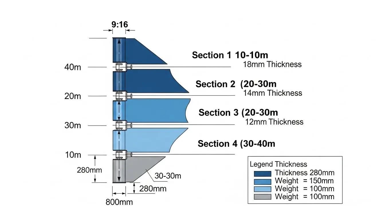
Let's break down a 40m tower as an example:
| Section | Height Range | Diameter Range | Wall Thickness | Section Weight | Connection Type |
|---|---|---|---|---|---|
| Section 1 (Base) | 0-10m | 800mm-650mm | 18mm | 2,100 kg | Base plate to foundation |
| Section 2 (Lower-Mid) | 10-20m | 650mm-520mm | 14mm | 1,800 kg | Flange or overlap |
| Section 3 (Upper-Mid) | 20-30m | 520mm-400mm | 12mm | 1,500 kg | Flange or overlap |
| Section 4 (Top) | 30-40m | 400mm-280mm | 10mm | 1,200 kg | Flange connection |
The connection type affects thickness at joint locations. Overlap connections need 1.5-2mm additional thickness where sections telescope together. Flange connections require reinforcement plates but keep standard wall thickness.
Manufacturing tolerance is typically ±0.5mm on wall thickness. We use ultrasonic testing to verify thickness across the entire steel plate before cutting. Any variance beyond 0.5mm gets rejected—it matters that much for structural calculations.
For projects requiring galvanization thickness specifications, the base metal thickness determines coating adhesion quality. Thinner sections (under 8mm) require careful galvanizing temperature control to prevent warping.
Wall Thickness Requirements by Wind Zone
Wind zone classification changes everything about thickness specs.
The U.S. uses ASCE 7 wind maps with four zones. Europe uses Eurocode EN 1991-1-4. China uses GB 50009. They all classify wind intensity differently, but the principle stays the same: higher wind speed requires thicker steel.
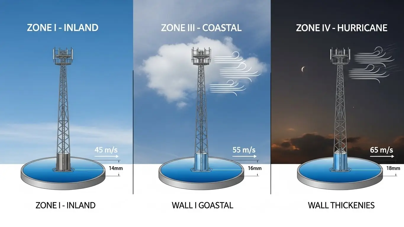
| Wind Zone | Design Wind Speed (m/s) | Base Thickness Increase | Typical Regions | Standard Reference |
|---|---|---|---|---|
| Zone I | 40-45 m/s | Standard (baseline) | Inland, low elevation | ASCE 7 Fig. 26.5-1A |
| Zone II | 45-50 m/s | +0-5% | Standard regions | GB 50009 Table 8.2.1 |
| Zone III | 50-55 m/s | +10-15% | Coastal areas | TIA-222-G Section 2.6.6 |
| Zone IV | 55-60+ m/s | +20-25% | Hurricane zones, mountains | ASCE 7 Section 26.5.2 |
| Coastal/Typhoon | 60-70 m/s | +25-30% | Southeast Asia, Gulf regions | GB 50135 Section 7.2 |
Here's what this means in practice: A 30m tower needing 14mm base thickness in Zone I would require 16mm in Zone III and 18mm in coastal typhoon regions.
Ice loading adds another layer of complexity. Areas with heavy ice accumulation (northern climates, high altitude) need 10-15% thickness increase. The ice doesn't just add dead weight—it increases the wind surface area dramatically. A 25mm ice coating can double the effective diameter for wind load calculations.
Our projects in Southeast Asia and Africa typically fall into Zone III-IV ranges. We automatically spec thicker base sections (16-18mm minimum for 30m towers) because tropical storm patterns are unpredictable.
Material Grade Impact on Wall Thickness
Not all steel performs the same. The grade you specify directly affects required thickness.
Steel grades are classified by yield strength. Higher yield strength means the material can handle more stress before permanent deformation. This lets you use thinner walls for the same structural performance.
| Tower Height | Q235 Base Thickness | Q345 Base Thickness | Q420 Base Thickness | Weight Savings with Q345 |
|---|---|---|---|---|
| 20m | 14mm | 12mm | 10mm | 15% |
| 30m | 16mm | 14mm | 12mm | 14% |
| 40m | 20mm | 18mm | 16mm | 12% |
| 50m | 24mm | 22mm | 20mm | 10% |
| 60m | 28mm | 25mm | 22mm | 12% |
Material grade specifications:
- Q235 (A36 equivalent): 235 MPa yield strength, most economical, requires thicker walls
- Q345 (A572 Gr.50): 345 MPa yield strength, industry standard, balances cost and performance
- Q420 (A709 Gr.50): 420 MPa yield strength, premium grade, allows minimum thickness
- Q460: 460 MPa yield strength, specialized applications, highest cost
We manufacture 85% of our monopole towers using Q345 steel. It's the sweet spot—strong enough to keep thickness reasonable, available enough to control costs, weldable enough to maintain quality.
The cost difference is about 8-12% between Q235 and Q345 per ton, but the weight savings (10-15%) on thinner sections offset this. You also save on transportation, foundation loads, and installation crane requirements.
For bolt specifications in tower construction, higher grade steel base plates require fewer and smaller diameter anchor bolts due to better stress distribution.
Engineering Standards and Specifications
Every country has different engineering codes. Your tower needs to comply with local standards, not just the manufacturer's preference.
United States:
- ASCE 7: Wind and seismic load calculations
- TIA-222-G (now TIA-222-H): Telecommunication tower structural standards
- ASTM A123: Hot-dip galvanization specification (85μm minimum)
- AISC 360: Steel construction manual
Europe:
- EN 1993-3-1: Towers and masts structural design
- EN 1991-1-4: Wind actions on structures
- EN ISO 1461: Galvanization specification (70μm minimum)
- EN 1998: Seismic design requirements
China:
- GB 50135: Code for design of high-rising structures
- GB 50009: Load code for design of building structures
- GB/T 13912: Galvanization thickness specification (85μm minimum)
- GB 50011: Code for seismic design
International:
- IEC 60826: Design criteria for overhead transmission lines
- ISO 9001: Quality management system
- ISO 14001: Environmental management
Our engineering team maintains certifications in all major standards. When you order from X.Y. Tower, we provide stamped calculations showing compliance with your specified code—whether that's TIA-222 for U.S. projects or GB 50135 for Chinese installations.
The certification documents matter for project approval. We include: material test certificates (MTC), galvanization thickness reports, weld quality inspection records, and final dimensional verification.
How to Calculate Wall Thickness for Your Project
You can't just pick a number from the chart and call it done. Every project has unique requirements.
Here's the step-by-step process our engineers use:
Step 1: Define Your Parameters
- Tower height (centerline to top)
- Equipment load (antennas, platforms, cables)
- Wind zone classification
- Ice accumulation thickness (if applicable)
- Seismic zone rating
- Service life requirement (20, 30, or 50 years)
Step 2: Calculate Design Wind Speed Use ASCE 7 maps or local meteorological data. Convert to 3-second gust speed at top of tower height. Apply exposure category correction (B, C, or D terrain).
Step 3: Determine Wind Loads Calculate wind pressure: P = 0.613 × V² × Kz × Kd × I
Where:
- V = wind speed (m/s)
- Kz = height coefficient
- Kd = directional factor
- I = importance factor
Step 4: Add Equipment Loads Sum antenna areas, cable weight, platform loads, ice accumulation. Apply appropriate load factors (typically 1.6 for wind, 1.2 for dead load).
Step 5: Run Structural Analysis Calculate maximum moment at base: M = P × H × (H/2)
Determine required section modulus: S = M / (σ × safety factor)
Step 6: Select Wall Thickness Choose thickness that provides adequate section modulus with 2.5-3.0 safety factor. Verify against buckling criteria. Check deflection at top (usually limited to H/100).
Example: 30m Tower in Wind Zone II
- Height: 30m
- Wind speed: 47 m/s
- Equipment: 12 antennas, total 450 kg
- Location: Standard inland
- Steel: Q345
Wind pressure at top: 1,400 N/m²
Total wind load: 18,500 N
Base moment: 277,500 N⋅m
Required thickness: 14mm base, 12mm mid, 8mm top
Most engineers use specialized software (PLS-TOWER, TOWER, or STAAD.Pro) for final verification. The hand calculations get you close, but software accounts for dynamic effects, connection eccentricities, and complex load combinations.
If you're unsure, consult a structural engineer licensed in your jurisdiction. The cost of calculation review (typically $800-2,000) is nothing compared to tower failure liability.
Thickness vs. Tower Performance Comparison
Thicker isn't always better. There's a performance curve where additional thickness provides diminishing returns.
| Base Thickness | Max Recommended Height | Antenna Load Capacity | Wind Resistance | Expected Fatigue Life |
|---|---|---|---|---|
| 10mm | 20m | 800 kg | 45 m/s | 20-25 years |
| 12mm | 25m | 1,100 kg | 50 m/s | 25-30 years |
| 16mm | 35m | 1,800 kg | 55 m/s | 30-40 years |
| 20mm | 45m | 2,500 kg | 60 m/s | 40-50 years |
| 25mm | 60m | 3,500 kg | 65+ m/s | 50+ years |
Load capacity increases roughly proportional to thickness squared. Doubling thickness from 10mm to 20mm increases capacity by about 3.5×, not 2×. This is because both material strength and geometric section modulus improve.
Wind resistance improves linearly with thickness up to a point. Beyond that, diameter and taper angle matter more than wall thickness. A well-designed 16mm tower can outperform a poorly designed 20mm tower in high winds.
Fatigue life extends significantly with thicker walls. Cyclic loading from wind causes microscopic cracks over time. Thicker sections have more material before cracks reach critical size. This is why coastal towers (constant wind cycling) need thicker specifications than inland towers.
We've tracked performance data on our towers installed since 2008. The 30m towers we supplied with 14mm Q345 base sections show zero structural issues after 15+ years in Zone II regions. The ones in coastal Zone IV with upgraded 16mm thickness have performed equally well despite harsher conditions.
Maintenance requirements decrease with proper thickness specification. Thin-walled towers (under-designed) develop stress cracks requiring weld repairs within 5-10 years. Properly specified towers run maintenance-free for 20+ years except for routine galvanization inspection.
Special Applications and Thickness Modifications
Standard charts don't cover every scenario. Some projects need custom thickness specs.
Camouflaged Monopoles
Tree pole and flag pole disguises add aerodynamic complexity. The fake branches or flag fabric create asymmetric wind loading. Base sections typically need +2-3mm thickness increase, and we add stiffener rings at branch attachment points.
Our projects in urban Africa and Southeast Asia use camouflaged towers extensively for aesthetic requirements. The monopole tower designs incorporate hidden platforms and reinforced mounting points that standard specifications don't address.
Multi-Operator Towers
When multiple carriers co-locate on one tower, equipment loads can double or triple. A single-operator 40m tower with 1,500 kg antenna load becomes a 2,800 kg multi-tenant installation. This requires:
- +15-20% base thickness increase
- Reinforced platforms and mounts
- Enhanced foundation design
- Upgraded anchor bolt sizes
Extreme Height Towers (60m+)
Beyond 60m, monopole design shifts significantly. We've manufactured 75m and 80m monopole towers for specific broadcast applications. These require:
- 28-32mm base thickness
- Five or six sections instead of four
- Enhanced flange connections with gusset plates
- Foundation analysis for differential settlement
- Dynamic analysis for vortex shedding
Seismic Zones
High seismic regions (California, Japan, Chile, Indonesia) need ductility more than pure strength. The steel must absorb earthquake energy without brittle fracture. This means:
- Minimum thickness regardless of height (12mm base even for 20m towers)
- Q345 or higher grade steel (Q235 too brittle)
- Special welding procedures for ductility
- Base plate designed for plastic hinge formation
Corrosive Environments
Coastal, industrial, or high-humidity environments accelerate corrosion. Besides galvanization, thickness provides sacrificial material. We recommend:
- +1-2mm thickness allowance for corrosion loss
- 120μm galvanization instead of standard 85μm
- Epoxy coating over galvanization for extreme cases
- Annual inspection program
Projects in Africa's coastal regions (Nigeria, Ghana, Mozambique) get automatic thickness upgrades and enhanced galvanization due to high salinity and humidity.
Common Thickness Selection Mistakes to Avoid
We see the same errors repeatedly when reviewing competitor designs or client RFQs.
Mistake #1: Using Uniform Thickness
Some manufacturers quote single thickness for the entire tower to simplify production. A 40m tower with uniform 16mm thickness weighs 9,800 kg versus 7,200 kg with proper tapering. You're paying for 2,600 kg of unnecessary steel plus increased foundation loads.
Mistake #2: Ignoring Local Wind Data
Generic Zone II specifications don't account for local wind patterns. Coastal areas 50km inland might still get Zone III winds from sea breezes. Mountain gaps create wind tunnel effects. Always check meteorological data for your specific site.
Mistake #3: Forgetting Future Equipment
Today's 800 kg antenna load becomes 1,200 kg when carriers upgrade to 5G. Spec for 125-150% of current load to avoid costly reinforcement later.
Mistake #4: Wrong Material Grade
Specifying Q235 to save 10% on material costs then needing 15% more thickness makes no sense. Q345 is almost always more economical in total installed cost.
Mistake #5: Inadequate Connection Thickness
The wall might be 14mm, but the flange plate is 12mm. The connection becomes the weak point. Flange plates should match or exceed wall thickness.
Mistake #6: No Engineering Review
Using catalog specifications without site-specific analysis. Every tower installation has unique soil conditions, wind exposure, and load requirements that affect thickness selection.
Mistake #7: Cheapest Bid Wins
We've seen projects fail because procurement chose the thinnest legal specification. The tower met minimum code but had zero safety margin. A 500 kg equipment addition exceeded capacity, requiring expensive reinforcement.
The cost difference between proper specification and minimum specification is typically 5-8% of tower cost. The risk of failure or modification cost is 200-500% of tower cost. The math is simple.
Frequently Asked Questions
The practical minimum wall thickness for structural telecom monopole towers is 6mm for top sections of shorter towers (15-20m height). While 3-4mm thickness exists in lightweight applications like camera poles, 6mm is the industry standard minimum for towers supporting telecommunications equipment. Base sections should never use less than 10mm thickness regardless of tower height. This minimum ensures adequate strength, prevents manufacturing defects during forming, and provides sufficient galvanization adhesion surface.
Base sections should be 2-3 times thicker than top sections as a general rule. For example, a tower with 8mm top thickness typically requires 16-20mm base thickness depending on height and wind loads. The exact ratio depends on tower height—taller towers need proportionally thicker bases. A 20m tower might have a 2× ratio (12mm base, 6mm top) while a 50m tower needs closer to 3× (22mm base, 8mm top). This progressive thickness distributes material where stress concentrates most.
Wall thickness dramatically impacts total weight. A 30m tower with uniform 16mm thickness throughout weighs approximately 8,500 kg. The same tower height with tapered thickness design (16mm base, 12mm mid, 8mm top) weighs only 6,200 kg—a 27% weight reduction. This saves on material costs, reduces transportation expenses, lowers foundation requirements, and decreases installation crane capacity needed. The weight savings from proper thickness tapering typically offset any additional engineering or fabrication complexity.
Yes, higher grade steel allows thickness reduction while maintaining equivalent structural strength. Q345 steel (345 MPa yield strength) permits approximately 10-15% thickness reduction compared to Q235 steel (235 MPa yield). For example, a section requiring 16mm Q235 thickness can often use 14mm Q345 thickness. However, minimum thickness limits still apply—you can't reduce below 6mm for top sections regardless of grade. The cost premium for higher grade steel (8-12% more per ton) is usually offset by weight savings and reduced fabrication costs.
Coastal installations require 15-20% thickness increase over standard inland specifications due to higher wind loads and accelerated corrosion from salt exposure. A standard 30m inland tower with 14mm base thickness needs 16-17mm for coastal locations. Beyond thickness, coastal towers also need enhanced galvanization (100-120μm instead of 85μm minimum) and sometimes additional epoxy coating. Annual inspection programs are recommended for coastal towers to monitor galvanization condition and structural integrity. The thickness increase provides both structural margin and sacrificial material for corrosion loss.
Ice loading requires 10-15% thickness increase in affected climate zones. Ice accumulation adds significant dead weight plus increases wind surface area dramatically. A 25mm radial ice coating (50mm diameter increase) can double the effective wind load on the tower. Areas with regular ice storms, northern climates, or high-altitude locations need thicker specifications. Most engineers add 2mm to base section thickness and 1mm to mid-sections when ice loading exceeds 25mm radial thickness. The ice load combination (dead load + wind on ice-covered structure) often controls the design rather than wind alone.
25mm is the typical maximum for base sections of monopole towers up to 60m in standard conditions. However, extra-tall towers (60-80m), extreme wind zones (typhoon/hurricane regions), or heavy multi-operator equipment loads may require 28-35mm base thickness. Above 35mm wall thickness, the structural design often shifts to alternative configurations like lattice towers or reinforced monopoles with external stiffeners. Very thick walls (30mm+) create welding challenges, require special forming equipment, and have diminishing structural returns compared to diameter increases or higher grade steel.
Longer sections require 5-10% thickness increase compared to shorter sections due to reduced intermediate support. A tower built with 14m sections needs approximately 0.5-1mm additional thickness compared to the same tower built with 8m sections. Most manufacturers optimize around 10-12m section length as the best balance—long enough for efficient installation, short enough to keep thickness reasonable, and suitable for standard shipping containers (40ft). Section length also affects transportation costs and site accessibility. Very long sections (14m+) may not fit through narrow roads or gates.

Hey, I’m Chunjian Shu
"X.Y. Tower: Reliable, innovative solutions for high-quality towers and electrical equipment with professional service.