Tension Tower: Design & Applications for Power Transmission
2025-12-21
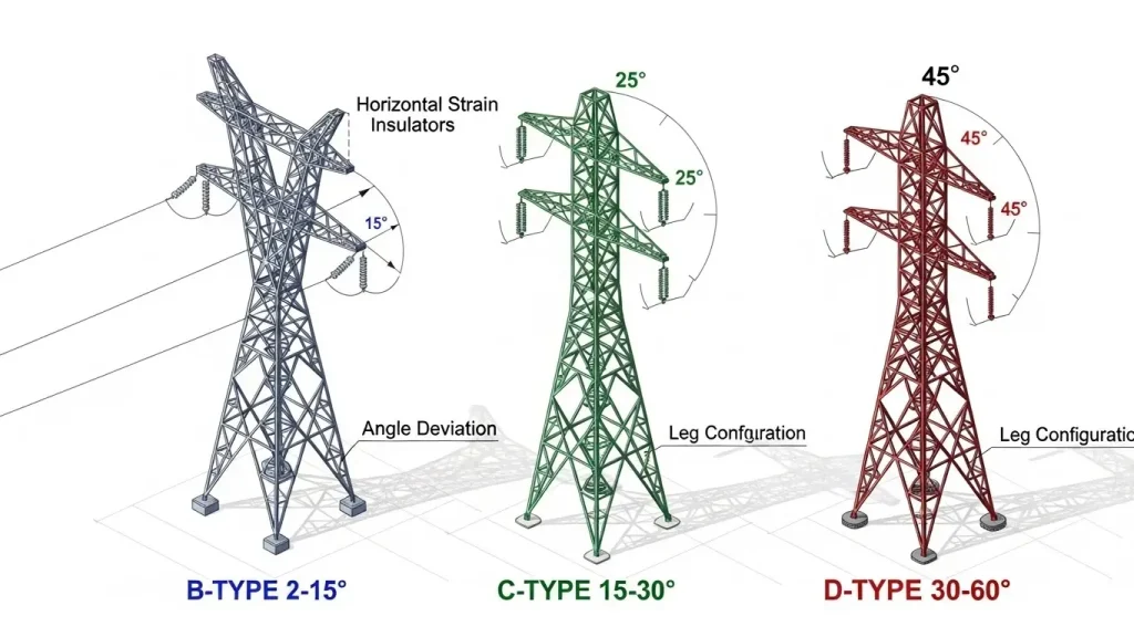
Tension towers are reinforced transmission structures that manage mechanical stress when power lines change direction beyond 2 degrees. These towers use horizontal strain insulators to resist longitudinal forces, classified as B-type (2-15°), C-type (15-30°), or D-type (30-60°) based on the angle of deviation required for your transmission line.
Unlike suspension towers that simply hang conductors vertically, tension towers anchor them firmly to prevent progressive line collapse. You'll need them at every directional change, with maximum spacing of 15 spans or 5 kilometers between installations.
What Makes Tension Towers Different
Here's what separates tension towers from standard transmission structures.
Tension towers pull on conductors instead of just supporting their weight. The insulators run horizontally, not vertically like you'd see on a suspension tower. This horizontal orientation lets them handle the pulling force when your transmission line makes a turn.
Most transmission lines use suspension towers for straight runs—they're lighter and cheaper. But the moment your line deviates more than 2 degrees, you need the reinforced structure of a tension tower. In our 17 years manufacturing towers at X.Y. Tower, we've seen projects fail because engineers tried to push suspension towers beyond their 2-degree limit.
The price difference tells the story. Tension towers cost 40-60% more than suspension towers because they need heavier steel reinforcement, larger foundations, and more complex insulator arrangements. But that extra investment prevents the cascade failure that can take down an entire transmission section.
B-Type, C-Type, and D-Type: Choosing Your Tower
Your angle deviation determines which type you need.
B-Type Tension Towers (2-15°)
B-type towers handle gentle directional changes with a two-leg design. You'll use these for:
- Gradual terrain following
- Minor route adjustments around obstacles
- Angles up to 15 degrees
Height ranges from 30-45 meters for 110kV lines, extending to 40-60 meters for 220kV transmission. With our 40,000 tons annual production capacity, we typically deliver B-type towers in 8-12 weeks depending on your specifications.
C-Type Tension Towers (15-30°)
C-type towers add a third leg for stability at medium angles. These work for:
- Valley crossings where terrain forces sharper turns
- Urban routing around dense development
- Angles from 15 to 30 degrees
Expect heights of 35-55 meters for 110kV and 50-70 meters for 220kV+. The three-leg configuration distributes loads more evenly than B-type towers, crucial for the increased lateral forces at these angles.
D-Type Tension Towers (30-60°)
D-type towers represent the heavy-duty option for sharp directional changes. You'll need these when:
- Crossing major terrain obstacles like ridges
- Making sharp turns to avoid protected areas
- Handling extreme angles from 30 to 60 degrees
These towers often use four-leg designs and can reach 55-80 meters for high-voltage applications. The foundation work alone can take 14 days per tower due to the massive loads involved.
Key Specifications by Voltage Level
Here's what you need to know for different voltage applications.
| Voltage | Height Range | Base Width | Conductor Clearance | Weight Range |
|---|---|---|---|---|
| 110kV | 30-60m | 5-10m | 7-9m | 15-30 tons |
| 220kV | 40-70m | 8-12m | 9-12m | 30-50 tons |
| 400kV | 50-75m | 10-15m | 12-15m | 50-80 tons |
| 500kV+ | 55-80m | 12-18m | 15-20m | 80-150 tons |
Our engineering team at X.Y. Tower designs every tower to meet GB, EN, and ASTM standards. The quality management system we maintain under ISO 9001 certification ensures consistent specifications across production runs.
The 15-Span Rule You Can't Ignore
Strategic spacing prevents catastrophic failures.
Place tension towers at maximum intervals of 15 spans or 5 kilometers—whichever comes first. This spacing creates sections that isolate conductor failures. If a wire breaks between two tension towers, only that section is affected. The rest of your line stays operational.
Between tension towers, you'll install lighter suspension towers. A typical section might look like this:
- Tension tower (start of section)
- Suspension tower
- Suspension tower
- Suspension tower (continue for up to 15 spans)
- Tension tower (end of section)
We've manufactured transmission line structures for projects across Africa and Southeast Asia where terrain forced sections shorter than 5 kilometers. That's fine—the 15 span/5km rule sets a maximum, not a minimum.
How Strain Insulators Work
The insulator configuration defines tower capability.
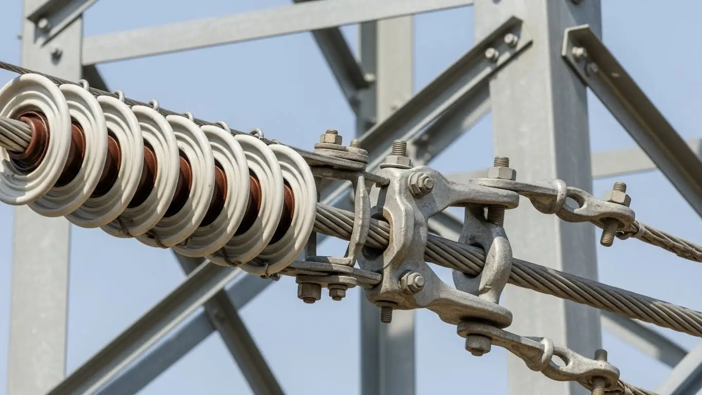
Strain insulators attach horizontally, pulling the conductor into the tower structure. Compare this to suspension insulators that hang vertically just supporting weight. This horizontal attachment creates a rigid anchor point that resists the pulling force when your line changes direction.
You'll see three main insulator materials:
- Glass disc strings: Traditional, visible damage inspection, 25-30 year lifespan
- Porcelain assemblies: Excellent pollution resistance, heavier than glass
- Composite polymer: Lighter weight, superior UV resistance, preferred for new installations
String length depends on voltage. For 110kV you need roughly 1.5-2.5 meters, extending to 6-9 meters for 500kV+ applications. Multiple parallel strings increase mechanical strength for high-load scenarios.
Special Application Requirements
Specific crossings demand exact clearances.
Railway Crossings
Your tower must sit at minimum distance of tower height plus 6 meters from the track centerline. Conductor clearance? 17.90 meters from the railway surface, no exceptions. Maximum span: 200 meters.
Double up your tension hardware and insulators at railway crossings. The redundancy protects against single-point failures over critical infrastructure.
Road Crossings
Maintain 12 meters minimum clearance from road surface to the lowest conductor. Again, double tension hardware and double insulators are mandatory for safety redundancy.
River and Valley Crossings
Modern river crossing tension towers can span up to 800 meters with zero-degree angle deviation. You'll need taller structures to achieve the necessary clearance and manage longer conductor spans.
For projects involving specialized applications like emergency communication towers or rooftop telecom structures, the clearance requirements change based on local regulations.
Material Specifications That Matter
Steel grade determines tower lifespan and load capacity.
We manufacture tension towers using four primary steel grades:
Q235B (370-500 MPa tensile strength)
- Light-duty applications
- Lower voltage lines (33-66kV)
- Cost-effective for simple installations
Q345B (470-630 MPa tensile strength)
- Medium voltage (110-220kV)
- Most common specification
- Best balance of strength and cost
Q420B (520-680 MPa tensile strength)
- High voltage applications (400kV+)
- Extreme environmental conditions
- Seismic zone installations
ASTM A572 GR65 (450-620 MPa tensile strength)
- International project standard
- Equivalent to Q345B
- Preferred for export projects
Our hot-dip galvanizing facility in Guanghan, Deyang applies minimum 86μm zinc coating thickness. This galvanization layer is what keeps towers standing for 50+ years in corrosive environments. We control the entire galvanizing process in-house, unlike manufacturers who outsource and lose quality oversight.
Standards Compliance Roadmap
Meeting international standards isn't optional.
Your tension towers need to comply with:
- IEEE 1070-95: Design and testing requirements
- IEC 60652: Loading test procedures
- ISO 9001:2015: Quality management systems
- GB/T 2694: Chinese national standards (if applicable)
Each tower undergoes comprehensive testing before leaving our facility:
- Bending tests to verify structural integrity
- Torsion resistance testing for wind loads
- Compression load testing on foundation interfaces
- Ultimate strength verification at critical connection points
- Galvanization thickness inspection at 10 random points
Testing documentation accompanies every shipment. Customers can witness factory testing—about 30% of our international clients choose this option.
Design Configurations for Different Conditions
Tower shape adapts to site requirements.
Cup-shaped design: Traditional configuration, optimal for moderate angles, easier transportation in sections
Cat-head shaped: Enhanced lateral stability, preferred for high wind zones, slightly heavier steel consumption
Upright configuration: Narrow footprint for restricted rights-of-way, requires deeper foundations, common in urban areas
Cantilever design: Asymmetric loading capability, useful near property boundaries, specialized engineering required
Barrel-shaped: Maximum strength for extreme angles, highest material cost, used for 45-60° applications
Site conditions drive the selection. Wind zone classification, seismic activity, soil bearing capacity, and available right-of-way all factor into the final design. Our engineering team runs PLS-TOWER analysis on every custom configuration to verify load paths and safety factors.
Cost Factors and Budget Planning
Understanding pricing helps project planning.
Tension towers run 40-60% more expensive than suspension towers per unit. But you need far fewer of them. A typical 100-kilometer transmission line might use 300 suspension towers but only 20-25 tension towers.
Key cost drivers:
- Material quantity: 15-150 tons depending on type and voltage
- Foundation complexity: Deeper, wider bases for higher loads
- Galvanization: Hot-dip process adds 12-15% to base steel cost
- Testing and certification: Quality control represents 5-8% of total
- Transportation: Sectional delivery reduces logistics costs
For current transmission tower pricing, material costs fluctuate with steel markets. Lock in pricing during procurement to avoid market volatility during your project timeline.
Total project cost breaks down roughly as:
- Tower manufacturing: 45-50%
- Foundation work: 25-30%
- Installation labor: 15-20%
- Testing and commissioning: 5-10%
Selection Framework for Your Project
Step through this process for the right tower specification.
Step 1: Map Your Route Survey the transmission line path and identify every point where deviation exceeds 2 degrees. Mark these as potential tension tower locations.
Step 2: Calculate Deviation Angles Use surveying equipment to measure exact angles at each turn. This determines whether you need B, C, or D-type towers.
Step 3: Check Spacing Verify that no section exceeds 15 spans or 5 kilometers. Add intermediate tension towers if necessary for section isolation.
Step 4: Match Voltage Requirements Select tower heights based on your voltage level and required ground clearance. Account for insulator string length in total height calculations.
Step 5: Evaluate Environmental Factors Check local wind zone classification, ice loading requirements, and seismic activity. These factors may require upgrading from standard specifications.
Step 6: Verify Foundation Conditions Conduct geotechnical investigation at proposed tower sites. Soil bearing capacity affects base width and foundation depth.
Step 7: Confirm Standards Identify which international standards apply to your project and region. Ensure your manufacturer can provide compliance documentation.
Step 8: Plan Installation Access Consider how tower sections will reach each site. Restricted access may require smaller section sizes for manual assembly.
Installation Timeline Expectations
Plan for these durations per tower.
Foundation Phase (7-14 days per tower)
- Excavation: 2-3 days
- Formwork and rebar: 2-3 days
- Concrete pour: 1 day
- Curing period: 7-10 days minimum
Tower Assembly (3-5 days per tower)
- Section delivery and positioning: 1 day
- Main structure erection: 1-2 days
- Cross-arm installation: 1 day
- Quality checks and touch-up: 1 day
Conductor Stringing (varies by section)
- Stringing equipment setup
- Wire pulling and attachment
- Tensioning to specifications
- Final sag adjustment
Weather delays add 20-30% to theoretical timelines in most climates. Monsoon regions require seasonal scheduling for foundation work.
Maintenance Requirements Over Time
Regular inspection prevents expensive failures.
Annual Visual Inspection
- Check for obvious corrosion
- Verify bolt tightness at critical connections
- Look for insulator damage or tracking
- Document any vegetation encroachment
5-Year Detailed Assessment
- Ultrasonic testing of welded connections
- Galvanization thickness measurement
- Foundation settlement survey
- Structural load testing if concerns arise
Post-Storm Emergency Inspection
- Immediate visual check after severe weather
- Priority inspection of high-stress components
- Document any permanent deformation
- Emergency repairs if needed for grid reliability
Drone technology has cut inspection costs by 30% compared to traditional climbing methods. High-resolution cameras identify issues that would take days to find manually.
Our towers rarely need structural repairs within the first 20 years if properly maintained. Galvanization touch-up at connection points represents the most common maintenance activity. Budget about 2-3% of initial tower cost for maintenance over a 50-year lifespan.
Frequently Asked Questions
Tension towers use horizontal strain insulators to resist pulling forces when transmission lines change direction beyond 2 degrees, while suspension towers use vertical insulators to simply support conductor weight on straight runs. Tension towers are 40-60% more expensive but prevent progressive line collapse and isolate sections for maintenance.
B-type towers handle 2-15° angle deviations with two-leg designs for gentle turns. C-type towers manage 15-30° angles using three-leg configurations for medium directional changes. D-type towers tackle extreme 30-60° deviations with heavy-duty four-leg structures. Your exact deviation angle at the tower location determines which type you need.
Maximum spacing is 15 spans or 5 kilometers, whichever comes first. This spacing creates isolated sections that prevent progressive collapse if a conductor fails. All towers between two tension towers are lighter suspension-type structures that cost less and install faster than tension towers.
Key standards include IEEE 1070-95 for design and testing, IEC 60652 for loading test procedures, and ISO 9001:2015 for quality management. Regional standards like GB/T 2694 in China or CIGRE in Europe may also apply. Compliance requires comprehensive testing including bending, torsion, compression, and ultimate strength verification before tower commissioning.
110kV tension towers range 30-60 meters in height, 220kV lines require 40-70 meters, and 400kV+ extra-high voltage applications need 50-80 meters. Exact height depends on voltage level, required ground clearance, insulator string length, conductor configuration, and specific terrain conditions at the installation site.

Hey, I’m Chunjian Shu
"X.Y. Tower: Reliable, innovative solutions for high-quality towers and electrical equipment with professional service.