
Angle Steel Towers: Designing for the Line, Not Just the Drawing
2026-07-27
The angle steel tower is not started from the workshop. It starts on the route of a transmission line at a point marked and designated.
There, the engineers already know that there the line goes straight, that it turns, or that it crosses difficult terrain or a substation. All those facts contribute to tower design, that is to say, the tower geometry, member forces, cross arm configuration, foundation reactions, and tower building sequence.
It is problematic to consider the tower as a "generic steel structure". Designing it as a site specific kit can provide a better predictability to its fabrication, transport and assembly.
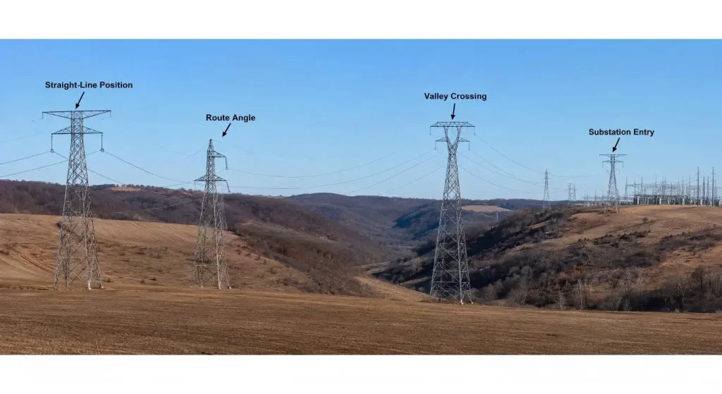
A project-specific transmission line steel tower should therefore be reviewed against the route geometry, loading conditions and erection constraints before fabrication drawings are released.
Freeze a Tower position prior to the steel being frozen
The first useful one is the tower schedule or spotting information which relates each tower to its route position.
The design team should validate tower function, tower route angle, conductor arrangement, electric clearances, profile of ground, body extension, leg extension, and concept of foundation.
The IEC 60826:2017/FM 52-17(DL/T 5582-2020/GB 50545-2010) specifies reliability criteria loading and strength requirements of overhead transmission lines and is applicable using climatic data on the local area under study. Therefore, site information can form part of the design-basis and is not an additional construction detail.
Elevation data from surveys may cause a tower to be relocated, altered or retuned if it was selected before the receipt of these data.
The control tower families and site variants are listed below
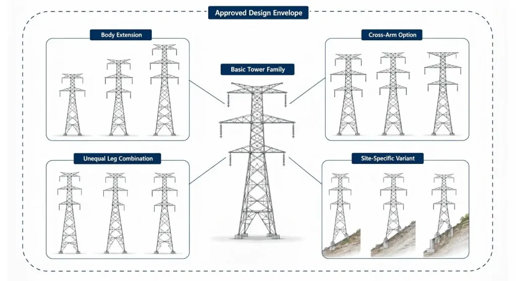
In transmission projects, the tower families are used as opposed to working out each tower by design. Several body extensions and/or unequal leg combinations and/or cross-arm options can be attached to the one basic tower.
Several body extensions, unequal-leg combinations and cross-arm options may be developed around one basic tower. This saves engineering time only when every permitted variant remains inside the approved design envelope. Where the available tower family no longer covers the actual site conditions, a controlled tower design solution is required instead of an informal member substitution.
Site variations shall not exceed the maximum envelope (tower-family) approved. Otherwise, the engineering review process is required but must be a specific engineering review and not simply a member substitution in lieu of an engineering review.
Rather than merely analyzing the data, use it to create ideas for improvement
Member forces given by structural analysis vs. factory built from detailing drawings.
ASCE/SEI 10-15 (DL/T 5154-2012)covers the design, fabrication and testing of the members and connections of latticed steel electrical transmission structures (compression members, tension members, fasteners, attachment holes, detailing and full scale testing).
The detail package must depict the member length, location of holes, assemble relationship, mark of members, orientation of angle and arrangement of bolt.
This is because good drawings minimize interpretation in the workshop and each physical member is easier to inspect.
Identify and design joints that can be used in actual assemblies
Angle steel tower has a large number of bolted joints. Some little problems with the connections add up.
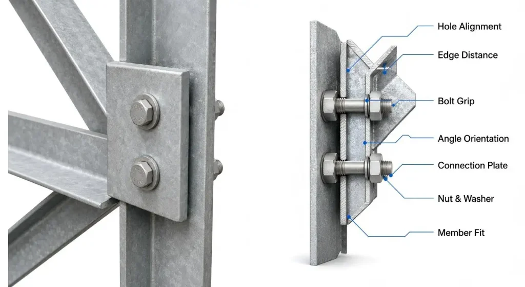
Holes and angles; plates must join without it being forced. The length of the bolt should be appropriate to the grip. After adjacent members are placed, there must be nuts and washers available. The general scope of requirements for execution of structural bolting specified in ISO 17607-6:2023.
When reviewing, inquire about the alignment, the sealing of the joint and where the inspection will take place. What was comfortable for a clean digital model may be a non-sensical (poor fit) on a tower face in poor weather.
Identify Material Before Manufacturing
In storage, cutting, punching and drilling, marking, galvanizing and bundling of angles and plates.
The present document ISO 630-1:2021 provides general technical delivery conditions for hot-rolled structural steel products which are used primarily for welded or bolted structures.
The factory should keep the traceability from material certificate until the mark of the finished product. This is of particular significance if multiple grades, thicknesses or projects are using the same workshop.Reliable transmission line services should connect design data, material control, fabrication inspection and final packing rather than treat them as unrelated workshop activities.
Galvanized items – only appearance will not reveal identity of material.
Treat Hole Quality as a Structural Detail
Making a tower isn't as straightforward as cutting steel to size.
Hole diameter, position, spacing and edge distance, burrs and local deformation must be controlled when punching and drilling. Wrong holes can lead to slower set up or generally put pressure on an erecter to enlarge holes at the site.
Specific points to inspect should be connection critical such as leg splices, cross arm attachments, diaphragms, tower peaks and foundation interfaces.
The use of either flame cutting or reaming the site unduly should never be considered a normal remedy for lack of proper fit in the factory.
If you're looking to get some practice together, this is a good way to do it with a few challenging papers:
Although factory assembly may not be required for an entire tower it may be required for critical sections.
The most obvious contenders are new tower heads, complex cross-arms, unequal-leg bases, special extensions and the first production units. The trial should replicate the alignment, the direction of the member, that bolts can access the piece, marking out of pieces, and interface dimensions.
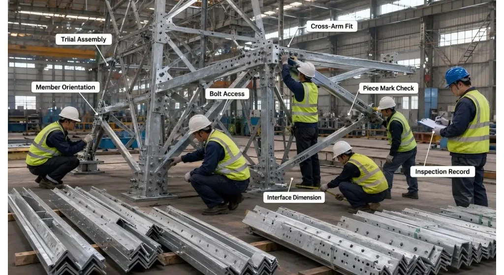
Any changes should be based on the controlled process of drawing and production. One inspection sample cannot be used to "repair" the remaining samples.
Galvanize without losing fit
When using hot dip galvanizing, fabricated tower steel is made corrosion resistant. ISO 1461:2022 covers the general properties and testing of the coatings on hot dip galvanized fabricated iron or steel articles.
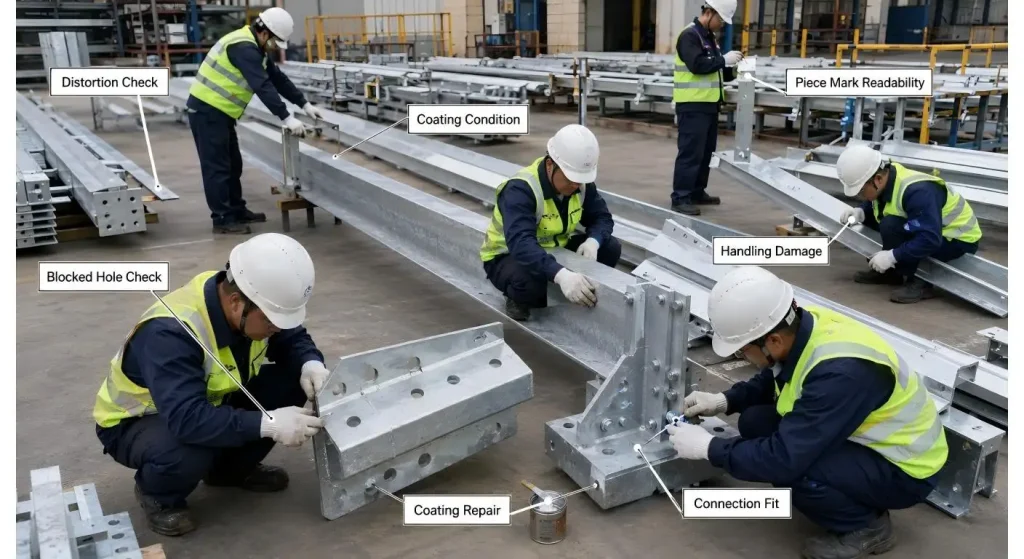
Fit can be impacted by the galvanizing process because holes can accumulate excess zinc, thin members can be distorted during the galvanizing process and surfaces may be damaged in the galvanizing process. Inspection should check the quality of the coating as well as features relating to assembly.
Allow for marks with coatings, as long as the piece mark is still legible, and coating repairs conforms to project specification.
Hot dip galvanizing is used to prevent corrosion of fabricated tower steel. All products are hot dip galvanized with the company's Hot-Dip Galvanizing Process Specifications and Hot Dip Galvanizing Work Instructions prepared in accordance with GB/T13912 (ISO 1461: 2022) and tested to meet or exceed the coating requirements.
Pack to follow the Erection Sequence
A tower can come in a variety of packages, and similar angles can vary merely in the number of holes or its length.
Piece marks must be legible following galvanising, transport and storage in the outdoor environment. Packing lists should be increased by either tower number (TW) or, if possible, erection section (SS).
Bolts, washers, step bolts, anti-climbing parts, earthing items, signs and small plates must be securely identified apart.
The optimal packing plan enables crew to locate the next member(s) without having to open all of the packing-bound bundles at the location.
The expected transmission line construction method should be reviewed before the packing plan is finalized, because road access, unloading equipment, lifting sequence and erection stages determine how tower members should be bundled.
To make sure that the Foundation Interface is verified soon
There is one unforgiving interface where the tower and foundation connect.
Determine base width, leg slope, stub setting, anchor layout, direction and extension combination and survey datum prior to letting too much concrete set.
Pre-erection records should determine foundation spacing, elevation, orientation and visible condition. Doing post factum galvanized tower leg modification is not a good alternative to early coordination.
| Project Hold Point | Required Evidence | Release Condition | Main Risk Prevented |
| Tower position freeze | Approved tower schedule, route angle and ground profile | Tower duty and site variant confirmed | Wrong tower assigned to the route |
| Detail drawing release | Member list, connection details and bolt arrangement | Drawings agree with structural analysis | Incorrect members or inaccessible joints |
| First production inspection | Hole, length, orientation and piece-mark records | Critical dimensions accepted before galvanizing | Site drilling, reaming or forced assembly |
| Trial assembly | Fit record and controlled correction list | Critical interfaces assemble without forcing | Repeated errors across the production batch |
| Post-galvanizing release | Coating, blocked-hole, distortion and marking report | Fit and identification remain acceptable | Assembly delay and unidentified components |
| Packing release | Bundle list arranged by tower and erection section | Members and small parts can be located in sequence | Opened bundles, lost parts and erection delay |
| Foundation handover | Base spacing, elevation, direction and stub records | Tower interface matches approved drawings | Tower-leg modification after concrete work |
| First tower review | Site assembly observations and issue log | Lessons incorporated into later shipments | Repetition of avoidable erection problems |
Investigate and experiment with the first house
For new or critical designs, full-scale loading tests can be performed to test the entire tower under certain loading conditions. IEC 60652:2021 covers methods and procedures to test overhead-line supports and structures, and does not cover reduced-scale models.
The structure tested shall be in accordance with approved design, members, connections and methods of fabrication.
The first tower built should be an opportunity to learn as well. Make notes of the following for further shipments: missing parts, difficult access, unclear marks, bundle problems, coating damage, lifting problems, survey problems.
Conclusion
When each stage in an angle steel tower ensures the protection of the same design intent, it is successful.
Routes data specifies the tower. Analysis is used to determine the forces. Detailing translates those forces into elements that can be constructed using. The information must be retained during fabrication, galvanizing, marking, packing, and during foundation work and erection.
The completed tower appears to be an easy design viewed from afar. From the survey point to the very last bolt is a series of hundreds of minor decisions which make or break its reliability.
FAQs
Q1. An Angle Steel Tower is what?
Mechanically strong structure; composed primarily of steel angle sections, plates and bolted connections; usually used for overhead transmission lines.
Q2. What is the significance of piece marks?Why is it important to have piece marks?
These link every member with its drawing number, record of materials used, list of members to be packed, tower number and erection position.
Q3. Does each Tower need to have trial assembly?
Not always. It's most effective with new designs, first production units, special heads, unequal leg bases and complicated interfaces.
Q4. What to Check After Galvanizing?
Examine coating condition and blocked holes, checking for distortion, readability of piece-mark, handling damage, and fit of critical connections.
Q5. The full-scale tower testing is applied when?
It can be defined for new, modified, critical, and representative designs per project and client requirements.

Hey, I’m Chunjian Shu
"X.Y. Tower: Reliable, innovative solutions for high-quality towers and electrical equipment with professional service.
