
Angle Steel Towers: Designing for the Line, Not Just the Drawing
2026-07-31
In most cases, an angle steel transmission tower needs to be combined with others. In fact, it's part of a line that can be made up of dozens, or even hundreds, of structures all with the same conductors but not necessarily performing the same function.
When it comes to how to purchase a tower, the good question for utilities and EPC contractors is not, “How much does one tower cost?” Answering this query is it: “How well does the proposed tower family cover the entire route?”
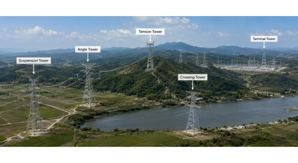
One Line Requires More than One Tower Duty.
Most of the transmission routes employ a controlled tower family and do not implement a unique design per site/pole.
The family consists of suspension, light-angle, heavy-angle, tension, terminal and crossing/transposition structures, as well as a number of body and leg extensions. This saves for the engineering and production time only if the duty range of each tower to hold is well established.
This is not acceptable if the suspension structure is required to be pushed in a tension position due to late changes in the route. Similarly, a tower that feels heavy, should not be accepted as a ‘terminal’ structure unless the load envelope can be checked as approved.
A transmission line steel tower proposal must specify the type of function, maximum allowed route angle, envelop of span, conductor arrangement and extension range for each type of the tower. These structures represent project-specific transmission products that can be modified to meet the needs for a site, terrain and environment, X.Y. Tower offers.
Start Out With Electrical Geometry
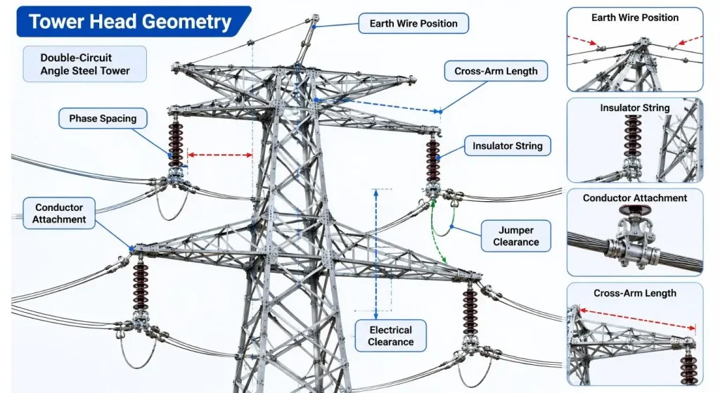
Prior to steel optimisation, the tower head is formed according to the electrical requirements.
The length of the cross arms and height of the towers will be determined by the required clearances and affected by phase spacing, conductor arrangement, length of the insulator strings, movement of the jumper, and the position of the earth-wire. The head geometry and structural loading can thus be impacted by a change in the hardware used—in the conductor or insulator.
This is one of the areas that can waste a project's time. Due to the two teams, civil and electrical, working asynchronously, civil can start foundation planning while electrical is still changing attachment levels. This then is submitted to the tower supply vendor as a “final” outline; even though it is not final.
Deliver the electrical configuration, route profile and hardware interfaces for freezing prior to delivery of detailed tower drawings. When designing, instead of chasing revisions, you can take the design from clearance to a buildable lattice.
Set up a Controlled Tower-Family Envelope.
A good tower family is flexible and can't be open-ended.
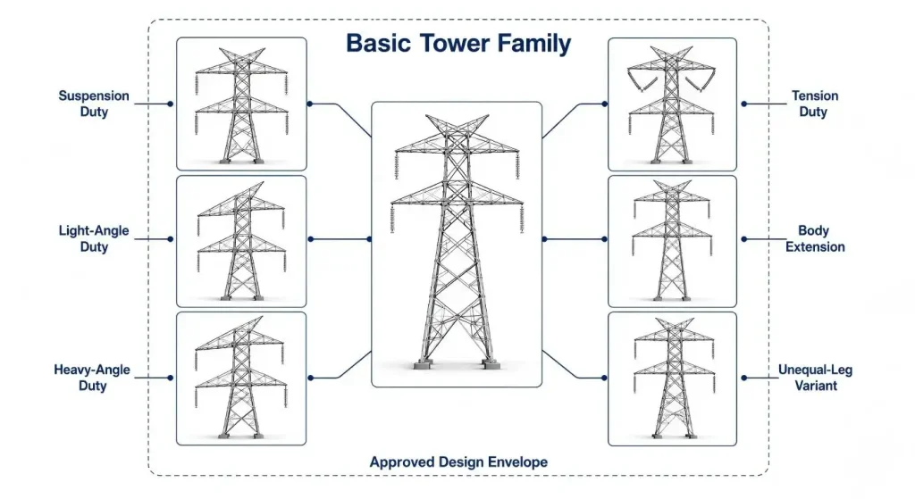
Limits for wind span, weight span, route angle, body extension, leg combination and conductors loading should have been specified by each basic tower. The out-of-range variants need to be addressed by a particular engineering review and not simply by switching out a couple of bigger members.
Within a tower design solution the relationship between the basic tower and its approved variants should be shown. X.Y. Tower's design service includes customized steel structures, tailored to project loading, environmental and installation needs.
In hilly corridors, a high-low leg tower may be useful to ride the slope of the land and result in less excavation. You may need to be identical to the survey, foundation setting and tower approved leg combinations.
Reliability based loading and strength criteria for overhead lines are given in IEC 60826:2017 which needs local climatic data for its application. It is not a substitute for the detailed design of the individual towers, foundations, conductor strings or strings of insulators.
| Tower Group | Route Duty to Confirm | Controlled Variables | Release Evidence |
| Suspension tower | Straight or limited-deviation section | Wind span, weight span and suspension hardware | Approved duty envelope and tower schedule |
| Angle tower | Route direction change | Deviation angle, conductor tension and jumper layout | Position-specific loading and clearance review |
| Tension or terminal tower | Anchor, section or line-end position | Longitudinal load, hardware and foundation reaction | Approved calculations and attachment drawings |
| Crossing or special tower | River, road, railway or critical span | Height, long span, security and construction loads | Dedicated engineering and client approval |
| Body extension | Additional tower height | Extension range, member changes and foundation loads | Approved extension drawing and material list |
| Unequal-leg variant | Sloping or irregular terrain | Leg combination, base level and survey orientation | Survey data and foundation interface record |
Ensuring that all site variants can be traced
There are dozens of towers in a route which are only one body extension or one combination of unequal legs away. This is adequate to produce a website problem with not a very powerful identification.
The tower number and variant code should be the same in the following documents: Tower schedule, calculation package, shop drawings, member lists, packing lists, and foundation records. If a tower position is changed then all linked documents should be changed accordingly.
In particular at anchor points it becomes important. This can be done using a tension tower if a line changes direction, terminates, or in areas that have steep changes in elevation and/or conductor forces. The hardware configuration, including the tower framing and tower (and foundation) reactions have to be fixed with the precise route location they were approved for.
A design change drawn up in the design office and not communicated to the factory/ foundation team is not a controlled revision.
In this project, a high school team conducts an experiment to verify the Tower family before the experiment is repeated
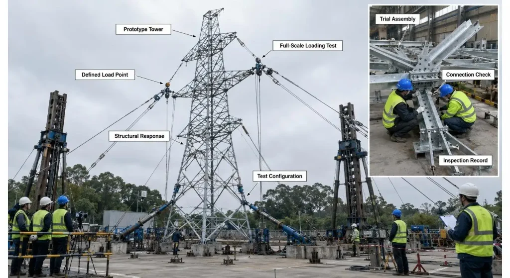
It is helpful to have a successful first assembly. A controlled prototype has much more to tell about the project.
Special extensions and unequal-leg bases, complex cross arms, and new tower heads must be tested before being produced in the large volumes that would show up in any product. The quality of fit, member orientation, bolt access and member interface size are checked in trial assembly.
If stipulated by the client or project specification, full scale loading tests are carried out to test the entire structure with certain loading arrangements. IEC 60652: 2021 General requirements for testing overhead-line supports and structures - Test methods and procedures, does not cover reduced scale model.
The basic guideline is very simple: don't ship one configuration and secretly produce another. Changes in the number of members, type of joints and method of fabrication should be considered as part of the project's change-control process.
Design-for-Production Protection Process
After the design of the tower is accepted, the factory needs to safeguard the design.
Traceability of material receiving, cutting, punching, trial assembly, galvanizing and packing in terms of steel grade and angle size, hole pattern, and mark of the members and bolt schedule should be traceable.
Although hot dip galvanizing is a method used for the protection of fabricated steel, inspection of the coating should never be a replacement for dimensional inspection. There is still the possibility that holes will be blocked, distortion and handling damage can occur and that marks will be unreadable.
This ISO specifies the general properties of and test methods for hot dip galvanized coatings on fabricated iron and steel articles. The project needs to establish the scope of the inspection; repair requirements; and special exposure requirement(s).
Provide Towers (+ Order the Line is to be built)
No warehouse transmission lines are installed.
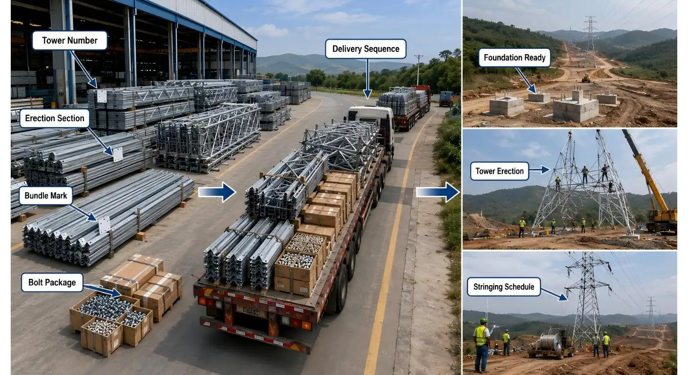
Those tower positions that must arrive first is determined by the access to the road, the readiness of the foundation and the erection crews and conductor-stringing plans. Associating all aspects in absolute size may be beneficial in the workshop, but at the site the team will be dealing with multiple bundles in order to make one structure.
Practical Delivery Plan includes the Tower Number, Erection Section, Bundle Mark and Bolt Package/drawing set. Small parts such as fittings, step bolts, grounding pieces and signs should be rolled and stored separately and not in random miscellaneous hardware.
As well as steel fabrication material, production, prototype, galvanizing and fastener & packing inspections, X.Y. Tower offers transmission line services.
Let's now check out the Supplier at Line Level
An excellent individual tower may still have issues putting together a whole route package offered by a supplier.
Inquire on the connection between positions on the tower and production batches. Inquire about the issuance of revisions, what happens to variants that are similar and how missing parts will be replaced. Automatically validate the traceability of the inspection documents to a tower number and a batch and shipment of material.
Different sections should also be specified in the quotation, such as design responsibility, prototype test, bolts, galvanising and packing, transport, site support & replacement parts etc.
This review is not as sensational as a tower loading test, but at the end of the day, it may be the difference between several hundred structures arriving as a controlled system vs several thousand unconnected pieces of steel.
Conclusion
Angle steel transmitting tower is no longer the galvanized lattice structure. It is a controlled member of a group of tower members and that group must meet the electrical geometry, route conditions and construction sequence of the line.
There are more benefits to improved tower functions that are established in advance and where revisions to tower designs can be tracked and prototype information is consistent with the production information.
The sequence of line can be repeated over many hundreds of kilometres. It is not to be repeated if the assumptions are unclear.
FAQs
Q1. The angle steel transmission tower is what?
It is a latticework unit (constructed largely from steel angle sections) used for supporting overhead conductors and is bolted in place. It can be a suspension, angle, tension, terminal or other specified transmission-line function.
Q2. Why Spokane uses tower families for transmission projects?
Using approved basic structures with controlled variants, design and manufacture activities are streamlined as Tower families are designed to minimise rework. All the variants should be within the geometry and loading limits stated.
Q3. Is there a tower design that can be used in all route positions?
No. Different types of towers and/or extensions may need to be used, depending upon requirements such as route angle, span length, terrain, conductor loading, electrical clearance and foundation conditions.
Q4. When will they need to be tested on Full Scale towers?
It is dependent on the project specification, novelty of the design and the client requirement. The tested structure should be the one used in production (the same one that has been approved).
Q5. What elements need to be listed in the RFQ?
Give the voltage, tower schedule, conductor and earth-wires information, span, route angles, climatic criteria, clearance, extensions, foundation interfaces, quantity and sequence.

Hey, I’m Chunjian Shu
"X.Y. Tower: Reliable, innovative solutions for high-quality towers and electrical equipment with professional service.
