Suspension Tower for Transmission Lines: Design & Applications
2025-12-23
Suspension towers support transmission line conductors in straight-line sections with deviation angles of 0-2 degrees, handling vertical loads of 15-45 kN per conductor. These towers represent 70-80% of structures in typical transmission projects and cost 30-40% less than tension towers. Built to IEC 60826 and ASCE 74 standards, they use lattice or monopole designs with hot-dip galvanized steel construction for 40-50 year service life.
In our 17 years manufacturing transmission infrastructure at X.Y. Tower, we've supplied suspension towers for projects across Africa, Southeast Asia, and South America. The demand for these structures continues growing as countries expand electrical grids and upgrade aging infrastructure.
What is a Suspension Tower? (Definition & Function)
A suspension tower is a transmission line support structure designed to carry the vertical weight of overhead conductors in straight-line route sections. Unlike tension towers that resist both vertical and horizontal forces, suspension towers primarily handle downward loads from conductor weight, wind pressure, and ice accumulation.
The key characteristic is their application in low-angle situations. When your transmission line route changes direction by less than 2 degrees, suspension towers are the optimal choice. Beyond this angle, you'll need tension or angle towers to handle the increased lateral loads.
Think of suspension towers as the workhorses of transmission systems. They're simpler, lighter, and more economical than other tower types. This is why they dominate most projects—using more suspension towers directly reduces your overall project costs.
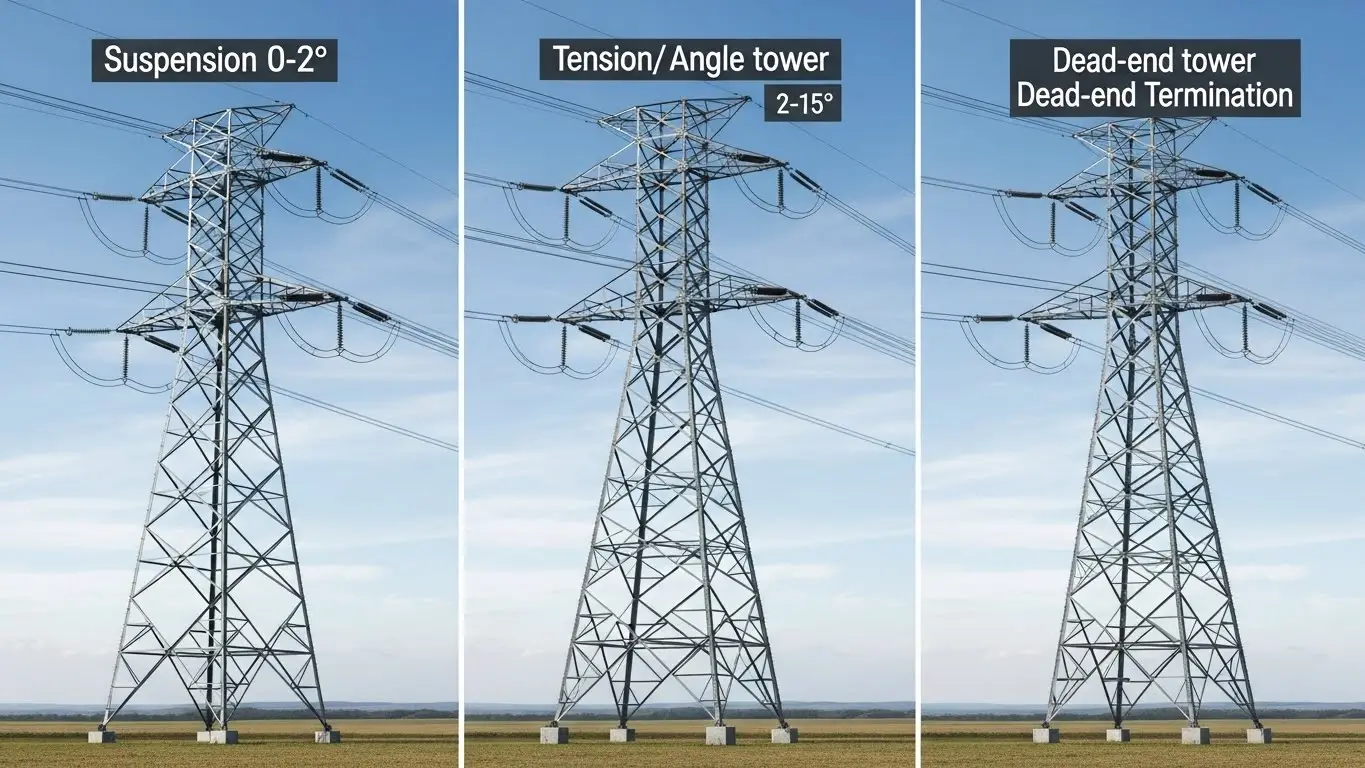
Quick Comparison: Tower Types
| Tower Type | Deviation Angle | Primary Loads | Typical Project % | Cost Factor |
|---|---|---|---|---|
| Suspension | 0-2° | Vertical only | 70-80% | 1.0x (baseline) |
| Tension | 2-30° | Vertical + horizontal | 15-20% | 1.4-1.6x |
| Dead-end | 30-90° or termination | Vertical + full tension | 5-10% | 1.8-2.2x |
Suspension Tower Design Types & Configurations
You'll encounter three main suspension tower configurations in the field, each suited to different project requirements.
Lattice-Type Suspension Towers
This is the most common design you'll see. Lattice towers use angular steel members assembled into a self-supporting framework. Our manufacturing facility produces both single-circuit and double-circuit lattice configurations, with square-base and delta (triangular-base) options.
Square-base towers work well for single-circuit lines and easier foundation construction. Delta configuration towers require less ground space and perform better in high-wind zones due to reduced wind load area.
For material specification, we typically use Q345 steel (yield strength 345 MPa) for standard applications and Q420 steel for high-loading situations. The higher strength steel reduces member sizes and overall tower weight, though material costs increase by approximately 15-20%.
Monopole Suspension Towers
Monopole designs use a single tubular steel shaft instead of lattice framework. These towers have become popular in urban areas where aesthetics matter and right-of-way width is limited.
The main limitation is span length. While lattice towers easily handle 350-450 meter spans for 132kV-220kV lines, monopole designs typically max out at 200-250 meters. Foundation requirements also differ—monopoles need larger diameter, deeper foundations to resist overturning moments.
Guyed Suspension Towers
For specialized applications like river crossings or mountainous terrain with extra-long spans, guyed suspension towers offer advantages. Steel guy wires anchored to the ground provide additional support, allowing lighter tower structures.
The trade-off is increased land requirements for guy anchor points. You'll need access to install and maintain these anchors, which isn't always feasible in developed areas.
Corrosion Protection Standards
All our suspension tower steel components receive hot-dip galvanization per ASTM A123 and ISO 1461 standards. This provides a minimum zinc coating of 610 g/m² (86 microns average thickness), delivering 30-50 years of corrosion protection in normal environments. Our integrated galvanizing facility with a 16-meter zinc bath ensures complete coverage even for large tower components.
Technical Specifications & Load Calculations
Understanding load calculations is critical for proper tower selection. Suspension towers must withstand three primary load types simultaneously.
Vertical Load Components
Dead load is straightforward—it's the permanent weight of conductors and overhead ground wires. For example, a typical ACSR (Aluminum Conductor Steel Reinforced) Drake conductor weighs 1.628 kg/m. With three conductors across a 400-meter span, you're looking at approximately 19.5 kN of conductor dead load alone.
Ice loading adds significant vertical weight in cold-climate regions. IEC 60826 specifies ice thickness based on climate zones. For moderate ice zones, calculate for 12.5mm radial ice thickness. Severe zones require 25mm or more. That same 400-meter span with 12.5mm ice adds roughly 8-10 kN per conductor.
Wind pressure creates both vertical (downward) and horizontal components. Basic wind speeds vary by region—IEC zones range from 34-42 m/s for normal areas, increasing to 50-55 m/s in cyclone-prone coastal regions.
Load Capacity by Voltage Class
Here's what you need to know for different voltage applications:
| Voltage Class | Typical Tower Height | Max Span Length | Vertical Load Capacity | Design Wind Speed | Ice Load Design |
|---|---|---|---|---|---|
| 66kV | 18-25m | 250-350m | 15-25 kN/conductor | 34-38 m/s | 12.5mm radial |
| 110kV | 22-30m | 300-400m | 20-35 kN/conductor | 36-40 m/s | 12.5-15mm radial |
| 132kV | 24-32m | 300-400m | 25-40 kN/conductor | 36-42 m/s | 12.5-20mm radial |
| 220kV | 28-38m | 350-450m | 30-45 kN/conductor | 38-44 m/s | 15-25mm radial |
| 330kV | 35-45m | 400-500m | 35-55 kN/conductor | 40-46 m/s | 20-25mm radial |
Combined Load Scenarios
The critical design case is rarely just one load type. Your suspension tower must handle combined scenarios like maximum ice load with moderate wind, or maximum wind with light ice.
Per IEC 60826, apply appropriate load combination factors. For instance, when combining maximum ice with wind, use 100% ice load with 50% of maximum wind pressure. This reflects real-world conditions where extreme values rarely occur simultaneously.
Safety factors also matter. Use a minimum 2.0 safety factor for structural members under normal loads, increasing to 2.5 for foundations and critical connections. These factors ensure your towers remain standing even when actual conditions exceed design assumptions.
Suspension Insulator Configurations
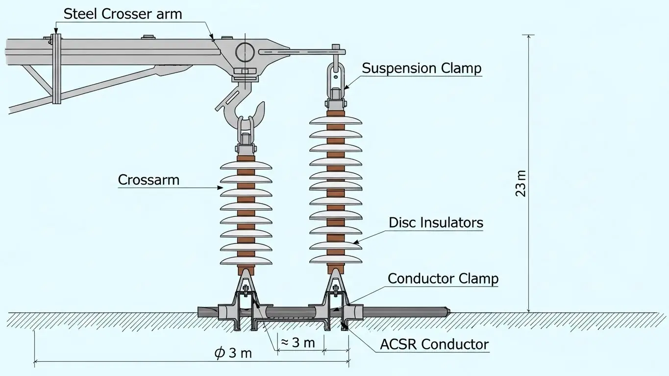
The insulator string is where conductors attach to your suspension tower. Getting this right affects both electrical performance and mechanical reliability.
Insulator Disc Quantities by Voltage
Suspension insulator strings use individual porcelain or glass disc insulators connected in series. The number of discs increases with voltage to maintain required electrical clearances and leakage distance.
Here's the standard configuration:
| Voltage Class | Number of Discs | Total String Length | Creepage Distance (mm) | Standard Reference |
|---|---|---|---|---|
| 66kV | 7-9 | 1.2-1.5m | 7,800-10,400 | IEEE 1427 |
| 110kV | 9-13 | 1.5-2.2m | 10,400-15,600 | IEC 60815 |
| 132kV | 13-16 | 2.2-2.7m | 15,600-19,200 | IEC 60815 |
| 220kV | 19-22 | 3.2-3.7m | 22,800-26,400 | IEEE 1427 |
| 330kV | 27-30 | 4.5-5.0m | 32,400-36,000 | IEC 60815 |
Each standard disc insulator has a 146mm diameter and 300mm minimum spacing. This is why total string lengths grow significantly at higher voltages—you need both electrical clearance and mechanical strength.
V-String vs. Single-String Configurations
For lines below 220kV, single suspension strings usually suffice. The conductor attaches to a clevis at the bottom of the insulator string, which hangs from the tower crossarm.
Above 220kV or in areas with heavy ice loading, V-string configurations provide better stability. Two insulator strings form a "V" shape, both connecting to the conductor. This arrangement resists swing and prevents galloping under wind and ice conditions.
Pollution Performance Considerations
If your project is in coastal areas, near industrial facilities, or in desert regions, pollution affects insulator performance. Salt spray, industrial emissions, and dust buildup reduce the electrical resistance of insulator surfaces.
For heavy pollution zones, use insulators with extended creepage distance—30-40mm per kV instead of the standard 20-25mm per kV. Anti-fog disc designs with deeper ribs also help maintain performance between cleaning cycles.
At X.Y. Tower, we source insulators from certified suppliers and can recommend appropriate specifications based on your project's environmental conditions.
When to Use Suspension Towers (Application Criteria)
Choosing the right tower type for each location along your transmission line route directly impacts project economics and long-term reliability.
Ideal Applications for Suspension Towers
Use suspension towers in these situations:
- Straight-line route sections where the transmission line continues in essentially the same direction
- Small angle points up to 2 degrees of direction change
- Flat to gently rolling terrain where span lengths remain relatively consistent
- Standard span lengths of 250-450 meters for 110kV-330kV applications
- Normal loading zones without exceptional wind or ice requirements
The 70-80% figure you often hear for suspension tower usage comes from real project data. On a typical cross-country transmission line, most of the route is straight with only occasional angle points. This is exactly where suspension towers excel.
When NOT to Use Suspension Towers
Switch to tension or angle towers when:
- Line deviation exceeds 2 degrees (use light-angle or medium-angle towers)
- Heavy side loads exist from unequal span lengths (deadend tension on one side)
- River crossings require longer spans with higher safety margins
- Road or railway crossings need stronger structures
- Line termination points or substation entrances
Real-World Project Example
Consider a recent 132kV transmission line project we supplied for a utility in East Africa. The 85-kilometer route included:
- 205 suspension towers (78% of total structures)
- 38 tension towers for angle points 2-15 degrees
- 14 heavy-angle towers for sharp turns 15-30 degrees
- 6 deadend towers for line termination and major crossings
This distribution is typical. The project achieved significant cost savings by maximizing suspension tower usage in suitable locations rather than over-engineering with heavier tower types throughout.
Decision Matrix for Tower Selection
| Line Condition | Deviation Angle | Span Difference | Recommended Tower Type | Reasoning |
|---|---|---|---|---|
| Straight section | 0-2° | <10% variance | Suspension | Most economical option |
| Small angle | 2-5° | <15% variance | Light tension/angle | Handles light lateral loads |
| Medium angle | 5-15° | Any | Medium tension/angle | Manages moderate lateral forces |
| Sharp angle | 15-30° | Any | Heavy angle | Withstands high lateral loads |
| Termination/crossing | Any | Any | Deadend | Maximum strength required |
Your route survey and profile drawings will show angle points clearly. During design, apply this matrix to select the optimal tower type for each position.
Design Standards & Compliance Requirements
Transmission tower design isn't optional—it must meet recognized international or regional standards to ensure safety and reliability.
International Standards Overview
The three most widely used international standards are:
IEC 60826 covers design criteria for overhead transmission lines. It specifies loading calculations, reliability requirements, and safety factors. Most countries outside North America reference IEC standards in their national codes.
IEEE 1427 provides guidance on electrical clearances for transmission lines. This standard helps you determine proper phase-to-phase spacing, phase-to-ground clearances, and insulator string lengths.
ASCE 74 (American Society of Civil Engineers Manual 74) presents guidelines for transmission line structural loading. While primarily used in the United States, its methodologies are respected globally.
Regional Standards Comparison
Different regions have adopted or adapted these international standards:
| Standard | Region | Key Requirements | Design Wind Speed Method | Ice Loading Approach |
|---|---|---|---|---|
| IEC 60826 | International | Reliability-based design | 3-second gust, mapped zones | Radial ice thickness by zone |
| GB 50545 | China | Deterministic with safety factors | 10-minute mean wind speed | Ice thickness + wind on iced conductor |
| IS 802 | India | Based on IEC with local conditions | 3-second gust, 4 wind zones | Light to moderate ice zones |
| AS/NZS 7000 | Australia/NZ | Performance-based design | Regional wind speed maps | Minimal ice (rare conditions) |
| EN 50341 | Europe | Harmonized EU requirements | National annexes vary | Climate-zone specific |
For export projects, clarify which standard applies during the tender stage. We've manufactured towers to all major standards and can adapt designs accordingly.
Compliance Checkpoints for Procurement
When specifying suspension towers, include these compliance requirements in your RFQ:
- Design standard and edition year (e.g., "IEC 60826:2017")
- Material standards for steel (e.g., "GB/T 700 Q345 or equivalent")
- Galvanizing standard (e.g., "ASTM A123 or ISO 1461")
- Testing requirements (prototype testing, galvanizing thickness tests)
- Documentation requirements (design calculations, material certificates, test reports)
Suppliers should provide certified calculations showing compliance with the specified standard. At X.Y. Tower, our engineering team uses industry-standard software for structural analysis and provides complete documentation packages with every project.
Cost Analysis: Suspension Towers vs. Other Types
Understanding tower costs helps you optimize your transmission line budget without compromising safety or reliability.
Suspension Tower Cost Ranges by Voltage Class
Based on current market conditions (2024-2025), here's what you should expect:
| Voltage Class | Suspension Tower Cost | Typical Tower Weight | Cost per Ton |
|---|---|---|---|
| 66kV-110kV | $6,000-$12,000 | 3-6 tons | $1,800-$2,200/ton |
| 132kV-220kV | $8,000-$25,000 | 5-12 tons | $1,600-$2,100/ton |
| 330kV-500kV | $20,000-$60,000 | 12-30 tons | $1,600-$2,000/ton |
These figures include materials, fabrication, galvanizing, and delivery to port. They don't include foundation construction, erection labor, or project management costs.
The wide ranges reflect different specifications. A basic 132kV single-circuit suspension tower for light loading will hit the lower end. A 220kV double-circuit tower designed for heavy ice zones reaches the upper range.
Comparative Cost Analysis: Tower Types
Here's where suspension towers show their value:
| Tower Type | Unit Cost (132kV example) | Typical % in Project | Cost Impact on 100km Line |
|---|---|---|---|
| Suspension | $12,000-$18,000 | 75% | $2.7M-$4.1M |
| Tension | $18,000-$28,000 | 20% | $1.1M-$1.7M |
| Deadend | $25,000-$40,000 | 5% | $0.4M-$0.6M |
| Total | Mixed types | 100% | $4.2M-$6.4M |
If you tried building that same 100km line using only tension towers (which are over-designed for straight sections), your tower costs would jump to $5.4M-$8.4M—a 30-50% increase with no performance benefit.
Factors Affecting Tower Costs
Several variables influence final pricing:
Steel prices fluctuate with global markets. Q345 steel costs have ranged from $650-$950 per ton over the past three years. When steel prices spike, tower costs rise proportionally.
Loading requirements drive design complexity. Heavy ice zones or extreme wind areas require more steel. A 132kV suspension tower designed for moderate conditions might weigh 7 tons, while the same voltage tower for severe ice and wind could reach 11 tons.
Transportation distance affects delivered costs. Shipping towers from China to East African ports costs $150-$250 per ton. South American destinations might be $200-$350 per ton.
Project volume provides economies of scale. An order for 200+ towers allows optimized production runs and better material pricing. Small orders (20-30 towers) carry 15-20% cost premiums.
At X.Y. Tower, our 40,000 tons annual production capacity and integrated manufacturing facilities (including our own galvanizing plant) help us maintain competitive pricing even during steel price increases. Learn more about our transmission tower pricing structure.
Installation & Foundation Requirements
Proper foundations are just as important as the tower structure itself. A perfectly designed tower will fail if its foundation can't handle the loads.
Foundation Types for Suspension Towers
You have three main foundation options:
Spread footing foundations work in competent soil with bearing capacity above 150 kPa. These are concrete pads that distribute tower leg loads over a wider area. For suspension towers, footing sizes typically range from 1.5m x 1.5m for lighter structures to 2.5m x 2.5m for heavier designs.
Each tower leg gets its own footing, positioned at the tower base width (usually 3-6 meters apart for suspension towers). Excavation depth runs 1.5-2.5 meters, depending on frost depth and soil conditions.
Pile foundations become necessary when soil bearing capacity is poor (below 100 kPa) or when groundwater levels are high. Driven or bored piles transfer loads to deeper, more competent soil layers.
For suspension towers, pile diameters of 300-600mm are common, with depths of 6-15 meters. Each tower leg typically requires 1-4 piles depending on loads and soil conditions.
Rock anchor foundations apply in rocky terrain where excavation for traditional footings would be expensive. Steel anchors are drilled and grouted into solid rock, with the tower legs bolted directly to the anchor plates.
This method works well in mountainous regions but requires careful rock quality assessment. Fractured or weathered rock won't provide adequate anchorage.
Soil Investigation Requirements
Before foundation design, you need soil data. Proper investigation includes:
- Test borings at 10-15% of tower locations (minimum every 2-3km)
- Bearing capacity determination through standard penetration tests (SPT)
- Groundwater level measurement
- Soil classification and properties
- Corrosion potential assessment for below-grade steel
Don't skip soil investigation to save costs. Foundation failures during or after construction are far more expensive than proper upfront engineering.
Installation Timeline and Equipment
A typical suspension tower erection takes 3-5 days with an experienced crew:
- Day 1: Site preparation, equipment positioning
- Day 2-3: Tower assembly and raising
- Day 4: Alignment, bolting, inspection
- Day 5: Conductor hardware installation
Required equipment includes a crane (capacity 15-40 tons depending on tower size), personnel lifts or climbing equipment, torque wrenches for bolt tensioning, and surveying instruments for alignment.
Maintenance & Inspection Guidelines
Regular maintenance extends your suspension towers' service life and prevents unexpected failures.
Inspection Intervals and Procedures
Follow a tiered inspection approach:
| Inspection Type | Frequency | Key Checkpoints | Required Actions |
|---|---|---|---|
| Routine visual | Annual | Visible damage, vegetation clearance | Document findings, clear minor issues |
| Detailed ground | 3-5 years | Bolt torque, corrosion spots, foundation | Retorque, treat corrosion, repair cracks |
| Detailed climbing | 5-10 years | All connections, member integrity | Full assessment, major repairs |
| Comprehensive | 15-20 years | Complete structural evaluation | Testing, rehabilitation planning |
The annual routine inspection can be done from the ground with binoculars. Look for obvious damage, missing hardware, corrosion bleeding, or vegetation growing too close to conductors.
Detailed inspections require tower access. Your crew should check:
- Bolt connections: Torque values can loosen over time. Re-torque critical connections per manufacturer specifications.
- Galvanizing condition: Look for areas where zinc coating has deteriorated, especially at welds and cut edges. Treat any bare steel with zinc-rich paint.
- Foundation stability: Check for cracks in concrete footings, settlement, or erosion around foundations.
- Conductor attachment points: Inspect insulator clamps, suspension clamp assemblies, and attachment hardware for wear.
Expected Service Life
Properly maintained suspension towers easily achieve 40-50 years of service. We've seen well-designed towers from the 1970s still operating reliably today.
The galvanizing is usually the first thing requiring attention. After 25-35 years in normal environments, you might need to perform maintenance painting or apply protective coatings to extend life another 15-20 years.
In harsh coastal environments, the same towers might need their first major maintenance at 15-20 years. Salt spray accelerates zinc coating consumption.
Preventive Maintenance Best Practices
Set up a database tracking each tower location, type, installation date, and inspection history. This helps you spot patterns and schedule maintenance efficiently.
Keep spare parts on hand: common bolt sizes, insulator discs, anti-climb devices, and galvanizing repair materials. Quick repairs prevent small issues from becoming major problems.
Train your maintenance crews properly. Tower climbing requires safety certification. Structural assessment needs engineering knowledge. Don't compromise on training to save money.
Common Design Challenges & Solutions
Even experienced engineers encounter situations that require creative solutions. Here are challenges we've helped clients solve.
Unequal Span Length Situations
Sometimes terrain forces significantly different span lengths on either side of a tower. A 350-meter span on one side and a 450-meter span on the other creates unbalanced vertical loads.
Standard suspension towers might not handle this asymmetry. Solutions include:
- Upgrading to a light-tension tower design that can resist the imbalance
- Using heavier conductor attachment hardware to transfer some load to the tower body
- Adjusting insulator string lengths to modify load distribution
Foundation Challenges in Difficult Terrain
Rocky slopes, wetlands, and unstable soil all complicate foundation construction. In mountainous areas with limited access, transporting concrete becomes expensive.
We've solved this by:
- Designing lighter towers that reduce foundation loads
- Using rock anchors instead of concrete footings in solid rock areas
- Specifying grillage foundations (steel framework) in areas where concrete delivery is impractical
- Recommending railway electrification tower designs for challenging terrain with proven performance
High Wind Zone Considerations
Coastal areas and mountain passes experience sustained high winds. Standard suspension tower designs may need reinforcement.
Options include:
- Reducing span lengths to decrease wind load on conductors
- Using delta-configuration towers with smaller wind-facing profile
- Specifying bundled conductors (multiple sub-conductors per phase) to reduce wind-induced vibration
- Adding dampers to control conductor galloping
For critical installations like emergency communication towers, these wind considerations become even more important.
Heavy Ice Loading Regions
Ice accumulation creates both weight and increased wind surface area. The combination can overload standard designs.
Engineering solutions:
- Increase tower and insulator string strength ratings by 25-35%
- Use insulator configurations that minimize ice bridging
- Specify conductor types with lower ice adhesion (smooth surface designs)
- Consider shorter spans to reduce total ice load per tower
Conductor Galloping Mitigation
Galloping is a low-frequency, large-amplitude conductor oscillation caused by wind on ice-covered conductors. It can damage insulators and even cause phase-to-phase contact.
Prevention methods:
- Install anti-galloping devices (interphase spacers, detuning pendulums)
- Use bundle conductors instead of single conductors
- Increase phase spacing where galloping history exists
- Consider compact tower designs with damping characteristics
How to Specify Suspension Towers for Your Project
Getting your specification right the first time saves weeks of back-and-forth with suppliers and prevents costly design changes during fabrication.
Essential Technical Information to Provide
Your RFQ should include:
Electrical parameters:
- System voltage and frequency (e.g., 132kV, 50Hz)
- Conductor type, size, and configuration (e.g., ACSR Drake, single conductor per phase)
- Overhead ground wire specification if applicable
- Phase spacing requirements
Mechanical parameters:
- Span length range (minimum, typical, maximum)
- Height requirements (conductor ground clearance needed)
- Tower type and quantity (e.g., 150 suspension towers)
- Foundation type preference
Environmental loading data:
- Basic wind speed or wind pressure at reference height
- Ice thickness requirement and concurrent wind
- Temperature range (affects conductor sag calculations)
- Seismic zone if relevant
Standards and certifications:
- Design standard (IEC 60826, ASCE 74, etc.)
- Material standards for steel and galvanizing
- Required testing (prototype, galvanizing samples)
- Documentation requirements
Supplier Evaluation Criteria
When comparing proposals, look beyond just price:
Technical capability: Does the supplier have in-house engineering? Can they provide certified calculations? What design software do they use?
Production capacity: Can they meet your delivery schedule? What's their annual output? Our 40,000 tons annual capacity and 180-employee team at X.Y. Tower ensures we can handle large projects without delays.
Quality systems: Look for ISO 9001 certification minimum. Ask about quality control procedures for welding, galvanizing, and final inspection.
Experience: How many similar projects have they completed? Can they provide references? We've supplied transmission infrastructure to over 30 countries since 2008.
After-sales support: Who handles technical questions during installation? Is field support available if issues arise?
For specialized applications like camouflage telecom towers or rooftop telecom structures, make sure your supplier has relevant experience.
Lead Time Expectations
Plan for these typical timelines:
- Engineering and approval: 4-6 weeks
- Production: 8-12 weeks (depending on quantity and complexity)
- Galvanizing: 2-3 weeks
- Shipping: 3-6 weeks (varies by destination)
Total procurement cycle from order to delivery: 4-6 months for standard projects. Rush projects with premium pricing might compress this to 3 months, but quality can suffer.
Frequently Asked Questions
Well-designed suspension towers with hot-dip galvanized protection last 40-50 years in normal environments. Coastal or industrial areas may see first major maintenance needs at 25-30 years. We've worked on rehabilitation projects for towers installed in the 1970s that remain structurally sound after proper maintenance. The key factors are coating quality, regular inspections, and prompt repair of any corrosion. Our galvanizing process follows ISO 1461 standards with minimum 610 g/m² zinc coating, providing decades of corrosion resistance.
Suspension towers comprise 70-80% of total structures in most projects. For a 100km transmission line with 350-meter average spans, you'd need about 285 total towers. Of these, approximately 210-230 would be suspension type, 40-60 would be tension towers for angle points, and 10-15 would be deadend towers for terminations and major crossings. The exact ratio depends on terrain and route alignment—straight routes in flat terrain push toward 80% suspension, while mountainous routes with many angles might drop to 65-70%.
Suspension towers accommodate very small deviation angles of 0-2 degrees maximum. Beyond 2 degrees, you must use tension or angle towers designed for lateral loads. Using a suspension tower at a 5-degree angle point would overload the structure and could lead to failure. During route planning, mark angle points clearly and specify the appropriate tower type. If you're unsure about deviation angles, your surveyor can calculate them from tower position coordinates along the route.
Single-circuit towers carry one three-phase power circuit (typically three conductors plus ground wires). Double-circuit towers carry two independent three-phase circuits on the same structure, effectively doubling capacity. Double-circuit designs are more economical than building two separate single-circuit lines when right-of-way is limited or expensive. However, they require stronger structures, wider bases, and more complex foundation systems, increasing unit costs by 60-80%. They're common in high-density corridors near urban areas. We've supplied both configurations for projects ranging from 25m telecom towers to 80m telecommunication towers.
Suspension towers are lighter and simpler because they only resist vertical loads, not horizontal forces from conductor tension at angle points. This reduces steel requirements by 30-40%, simplifies foundation design, and decreases installation time. For a 132kV project, suspension towers might cost $12,000-$18,000 each while equivalent tension towers run $18,000-$28,000. Since suspension towers form 70-80% of most projects, maximizing their use where appropriate delivers substantial total project savings without compromising reliabil

Hey, I’m Chunjian Shu
"X.Y. Tower: Reliable, innovative solutions for high-quality towers and electrical equipment with professional service.