Terminal Tower: Complete Guide to End-Point Power Line Structures
2025-12-24
Terminal towers are specialized transmission structures positioned at the endpoint of overhead power lines, connecting them to substation equipment using horizontal strain insulators. These self-supporting towers withstand full conductor tension ranging from 15-120 kN per phase depending on voltage level, making them 2-3 times more robust than standard suspension towers and essential for grid stability at critical connection points.
Unlike regular transmission towers that simply support line weight, terminal towers anchor the entire mechanical load where your transmission route ends. Here's what you need to know about these critical structures.
What is a Terminal Tower in Power Transmission?
A terminal tower marks the physical endpoint where your overhead transmission line connects to substation equipment or transitions underground. The defining characteristic? Horizontal strain insulators instead of the vertical suspension type you see on regular towers.
The structure must be completely self-supporting because there's no next tower in line to share the load. At X.Y. Tower, we've manufactured terminal towers for 110kV to 500kV systems across 20+ countries, and the engineering requirements are significantly different from mid-line structures.
Think of it this way: suspension towers carry weight, but terminal towers resist tension. When conductors pull from one direction with nothing to balance on the other side, you need serious structural reinforcement.
The typical terminal tower handles three distinct loads:
- Vertical load: Full weight of conductors without support from adjacent towers
- Horizontal tension: 15-120 kN per phase based on voltage and conductor type
- Torsional forces: Wind and weather effects on unbalanced line configuration
Most specifications require terminal tower foundations to be 30-40% deeper than suspension towers. We've seen foundation depths reach 250-280 feet for major 400kV installations where soil conditions demand caisson construction.
When and Where Terminal Towers Are Used
You'll need terminal towers in five specific situations. Let's break them down based on what we see in actual projects.
Substation connection points are the most common application. Every transmission line that enters a substation requires a terminal tower before connecting to the bus work. In our 17 years manufacturing towers, about 60% of terminal tower orders come from substation projects.
Overhead-to-underground transitions happen more often than you'd think. Urban areas, protected landscapes, or river crossings often require lines to go underground. The transition point needs a terminal tower to manage the change in conductor configuration.
Absolute line endpoints occur when a radial transmission line terminates at a remote facility like a mining operation or industrial plant. There's no substation—just an end-of-line connection to step-down transformers.
Branch circuit terminations use terminal towers (technically dead-end towers) where you're splitting off from a main line. The tower must resist pulls from both the main line and the new branch.
Strategic cascade prevention is less obvious but equally important. Transmission planners place terminal-type structures every 10-15 regular suspension towers. If one conductor fails, the cascade stops at the next dead-end point instead of collapsing the entire line.
Industry data suggests 15-25% of towers in a typical grid network are terminal or dead-end structures. That ratio increases in areas with complex terrain or multiple substations.
Terminal Tower vs Dead-End Tower: Key Differences
Here's where terminology gets confusing. Many engineers use "terminal tower" and "dead-end tower" interchangeably, but there are technical distinctions worth understanding.
A terminal tower specifically indicates the absolute endpoint where transmission terminates and connects to equipment. A dead-end tower (also called anchor or tension tower) can be mid-line at angle changes or placed periodically for cascade prevention.
Both use horizontal strain insulators. Both must be self-supporting and handle unbalanced loads. The difference is location and purpose, not structural design.
Here's the comparison that matters for your project:
| Parameter | Terminal Tower | Dead-End Tower | Suspension Tower |
|---|---|---|---|
| Primary Function | Line termination at substation | Angle change or cascade prevention | Straight-line support |
| Insulator Type | Horizontal strain | Horizontal strain | Vertical suspension |
| Load Capacity | 100% tension + weight | 100% tension + weight | Weight only (minimal tension) |
| Structural Weight | 8-15 tons (110kV) | 8-15 tons (110kV) | 3-6 tons (110kV) |
| Cost Multiple | 2.5-3x suspension | 2.5-3x suspension | Baseline |
| Foundation Depth | 30-40% deeper | 30-40% deeper | Standard |
| Typical Placement | Substation entry | Every 10-15 towers or angles >15° | Straight sections |
| Angle Capability | Not applicable | Up to 60° (D-type) | <2° (tangent) |
The practical reality? When you're getting quotes from manufacturers, many will list the same tower design under both names. What matters is the specification—horizontal strain insulators, self-supporting design, and adequate tension capacity for your voltage level.
At X.Y. Tower, our engineering team designs to your specific application. Whether you call it terminal or dead-end, we're focused on the mechanical requirements and site conditions.
Types of Terminal Tower Structures
Terminal towers come in several structural configurations. Your choice depends on voltage level, space constraints, and budget.
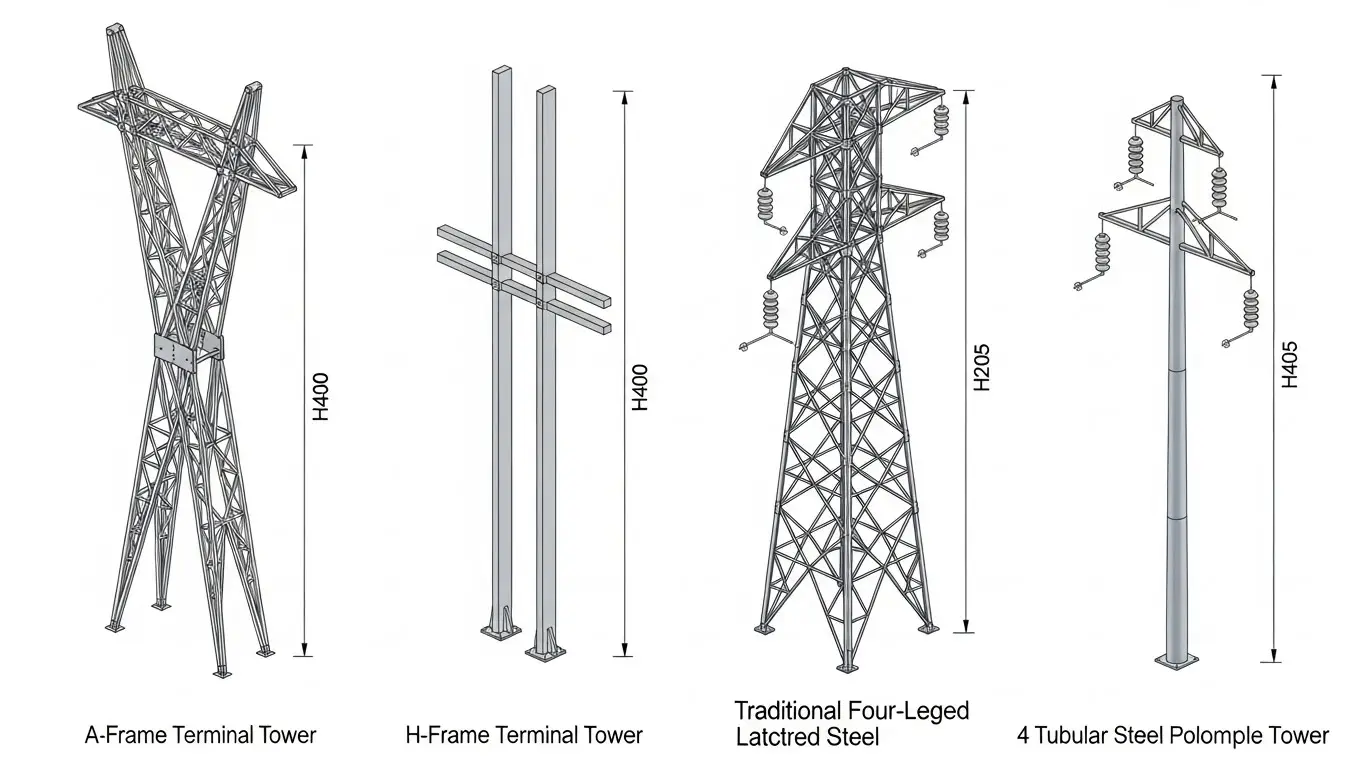
A-Frame terminal structures are the most economical design for voltages up to 220kV. Two steel members connect at the top in an "A" shape, with cross-arms for conductor attachment. We manufacture A-frame terminals in the 15-35 meter height range, typically for rooftop applications or compact substations.
The advantage is lower material cost and simpler foundation requirements. The limitation is reduced capacity for multi-circuit configurations.
H-Frame terminal structures use two vertical members connected by horizontal cross-beams. This design excels at 220kV-400kV applications where you need robust lateral strength. H-frames handle wind loading better than A-frames and allow for future circuit additions.
Our production data shows H-frame terminals average 12-18 tons for 220kV systems, with heights from 25-45 meters depending on conductor clearance requirements.
Lattice steel terminal towers are the traditional choice for high-voltage (400kV+) and extra-high-voltage (500kV+) systems. Four-legged lattice construction distributes loads efficiently and provides maximum structural stability.
With our 40,000-ton annual production capacity, we've optimized lattice tower manufacturing to keep costs competitive despite the higher material volume. A 400kV lattice terminal typically weighs 25-40 tons and stands 40-55 meters tall.
Tubular steel terminal poles offer aesthetic advantages in urban or scenic areas. The monopole design has a smaller visual footprint but requires precision engineering to achieve the same load capacity as lattice towers.
Tubular terminals work best for 110kV-220kV voltages where appearance matters. Installation is faster because you're dealing with pre-assembled sections rather than bolted lattice members.
Guyed vs self-supporting is another decision point. Guyed towers use guy wires to resist lateral loads, reducing steel requirements by 30-40%. They're cost-effective in rural areas with available space.
Self-supporting towers need no guy wires but use heavier construction. They're mandatory in substations and urban areas where guy wire anchor points aren't available.
Single-circuit vs multi-circuit affects tower width and cross-arm configuration. Multi-circuit terminals cost less per circuit than building separate towers, but they increase complexity if you're phasing construction over time.
| Tower Type | Height Range | Voltage Suitability | Typical Weight | Best Application | Installation Time |
|---|---|---|---|---|---|
| A-Frame | 15-35m | 110-220kV | 6-12 tons | Compact sites, budget projects | 3-5 days |
| H-Frame | 25-45m | 220-400kV | 12-18 tons | Standard substations | 5-7 days |
| Lattice Steel | 40-55m | 400-500kV+ | 25-40 tons | High-voltage systems | 10-14 days |
| Tubular Pole | 20-40m | 110-220kV | 8-15 tons | Urban/scenic areas | 4-6 days |
| Guyed Type | 30-50m | 110-400kV | 15-25 tons | Rural installations | 7-10 days |
Technical Specifications and Design Requirements
Let's get into the numbers that actually matter for your project. Terminal tower specifications vary significantly by voltage level, but the fundamental requirements remain consistent.
Voltage level categories drive most design decisions. Each step up in voltage requires greater insulator length, increased conductor spacing, and higher structural capacity:
| Voltage Level | Height Range | Insulator String Length | Conductor Tension Capacity | Foundation Depth | Wind Load Rating | Typical Weight |
|---|---|---|---|---|---|---|
| 110kV | 20-30m | 1.5-2.0m | 15-30 kN/phase | 6-8m | 160 km/h | 8-12 tons |
| 220kV | 30-40m | 2.5-3.5m | 30-50 kN/phase | 8-12m | 180 km/h | 15-22 tons |
| 400kV | 40-50m | 4.0-5.0m | 50-90 kN/phase | 12-18m | 200 km/h | 28-38 tons |
| 500kV | 45-55m | 5.0-6.5m | 70-120 kN/phase | 15-22m | 200 km/h | 35-50 tons |
Load capacity requirements break down into three categories. Vertical loads are straightforward—the full weight of your conductor span from the last suspension tower to the terminal point.
Horizontal loads come from conductor tension. At X.Y. Tower, we calculate this using the rated breaking strength (RBS) of your conductor multiplied by the safety factor specified in your design code. Typical safety factors range from 2.0 to 2.5.
Torsional loads result from asymmetric forces during high winds or ice events. Terminal towers at line endpoints experience more torsion than mid-line structures because loads aren't balanced.
Foundation requirements deserve special attention. Standard practice calls for foundations 30-40% more robust than suspension towers at the same voltage level.
Soil conditions drive the actual design. Sandy or weak soils require caisson foundations with diameters of 1.5-2.5 meters extending to bedrock or stable strata. Clay soils may allow spread footings with proper compaction.
We've shipped towers to projects requiring foundation depths from 6 meters (110kV in good soil) to 280 feet (400kV in challenging conditions). The foundation often costs more than the tower itself.
Material specifications follow international standards. We use Q345B steel (Chinese standard) equivalent to ASTM A572 Grade 50 for most applications. High-stress components may require Q420 or higher strength steel.
All our towers undergo hot-dip galvanization per ASTM A123 standards. Minimum coating thickness is 85 microns, but we typically achieve 100-120 microns in our dedicated galvanizing facility. This ensures 50+ year service life in most environments.
Clearance requirements vary by region but generally follow IEC or IEEE standards. Minimum phase-to-phase spacing increases with voltage, as does phase-to-ground and phase-to-tower clearances.
For 220kV, expect minimum 3.5-4.0 meter phase spacing. At 400kV, that increases to 6.0-7.0 meters. These clearances directly impact tower width and material requirements.
Insulator Systems for Terminal Towers
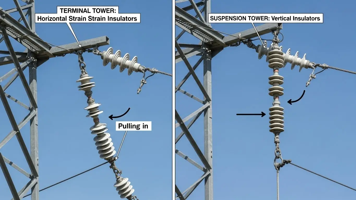
The insulator configuration makes or breaks terminal tower performance. Unlike suspension towers where gravity does the work, terminal insulators resist the full horizontal pull of your conductors.
Horizontal strain insulators are non-negotiable for terminal applications. These porcelain or composite polymer strings attach perpendicular to the tower, creating a direct tension path from conductor to structure.
Each insulator disc in a porcelain string handles mechanical loads around 160-210 kN depending on design. String length varies by voltage—you need more electrical creepage distance as voltage increases.
Porcelain vs composite polymers is an ongoing debate. Porcelain has proven reliability over 80+ years of field experience. It's heavier and more fragile during shipping, but replacement is straightforward because you swap out individual discs.
Composite insulators use fiberglass rods with silicone rubber sheds. They're 90% lighter than porcelain, resist vandalism better, and simplify installation. The tradeoff is less field history and potential for water ingress if the seals fail.
At X.Y. Tower, about 65% of our terminal tower projects now specify composite insulators. The weight savings during installation offset the slightly higher material cost.
| Voltage Level | String Length | Number of Discs (Porcelain) | Creepage Distance | Mechanical Load Rating | Typical Material |
|---|---|---|---|---|---|
| 110kV | 1.5-2.0m | 9-11 discs | 3,100-3,500mm | 160 kN | Porcelain/Composite |
| 220kV | 2.5-3.5m | 15-19 discs | 5,000-6,000mm | 210 kN | Porcelain/Composite |
| 400kV | 4.0-5.0m | 24-28 discs | 8,000-10,000mm | 300 kN | Composite preferred |
| 500kV | 5.0-6.5m | 30-38 discs | 10,000-13,000mm | 420 kN | Composite preferred |
Installation methods differ between tower types. Lattice towers typically use pin-type attachment at the cross-arm, allowing some rotation during installation. Tubular poles may use clevis attachments for simpler field work.
Maintenance considerations favor composite insulators in polluted environments. Porcelain requires regular washing in coastal or industrial areas to prevent flashover. Silicone rubber sheds on composite units are naturally hydrophobic and shed contamination better.
The mechanical strength rating must exceed the actual conductor tension by your code-specified safety factor. We typically see 2.5x safety factors, meaning a conductor pulling 60 kN requires 150 kN rated insulators minimum.
Standards and Compliance Requirements
Terminal tower design and manufacturing must comply with multiple standards depending on your project location. Here's what actually applies.
ASCE/SEI 48 (Design of Steel Transmission Pole Structures) is the primary US standard for tubular steel towers. It covers load calculations, foundation design, and structural analysis procedures.
ANSI/TIA-222-G (Structural Standards for Antenna Supporting Structures and Antennas) applies when terminal towers also support communication equipment. Our design software includes TIA-222-G analysis for these hybrid applications.
IEC 60826 (Loading and strength of overhead transmission lines) provides the international framework. Most countries outside North America reference IEC standards as the baseline.
GB/T 2694-2003 is the Chinese manufacturing standard we follow at our factory. It specifies steel grades, welding procedures, galvanization requirements, and quality control testing protocols.
For our international customers, we also certify compliance with EN standards (European) or AS/NZS standards (Australia/New Zealand) as needed.
ISO 9001:2015 quality management certification ensures consistent manufacturing processes. X.Y. Tower has maintained ISO certification since 2010, with annual audits by third-party assessors.
Testing and certification protocols include:
- Tensile testing of all steel materials
- Ultrasonic inspection of welds
- Galvanization thickness verification (minimum 5 points per member)
- Dimensional accuracy checks (±5mm tolerance)
- Load testing of sample structures to 150% design load
Documentation requirements for a typical terminal tower project include design calculations stamped by a licensed engineer, material certifications, welding procedure specifications, galvanization test reports, and final dimension verification.
Third-party inspection is common for projects over 220kV. Inspectors verify manufacturing quality before shipment and conduct field checks during installation.
Terminal Tower Cost Analysis and Pricing
Let's talk real numbers. Terminal tower costs vary widely based on voltage level, design type, and project specifics.
Base material costs for galvanized steel currently run $900-$1,360 per ton depending on steel grade and market conditions. Q235B (mild steel) is at the lower end, while Q420 high-strength steel pushes toward the upper range.
A 110kV terminal tower weighing 10 tons costs around $9,000-$13,000 in materials before fabrication. A 400kV tower at 35 tons runs $31,500-$47,600 in raw materials.
Manufacturing and galvanization add 40-60% to material costs. At X.Y. Tower, our 10 automated production lines keep fabrication costs competitive. Hot-dip galvanization in our dedicated facility adds $150-$200 per ton.
Total manufactured cost for a typical 220kV terminal tower (18 tons) runs $22,000-$32,000 FOB China.
Foundation costs often exceed the tower itself. A 110kV installation with good soil conditions needs $15,000-$25,000 in foundation work. Move to 400kV or challenging soil, and foundation costs reach $35,000-$60,000.
Caisson foundations for major projects can hit $80,000-$120,000 per tower, especially in seismic zones or weak soil areas.
Installation labor varies by region and tower complexity. Budget $8,000-$15,000 for 110kV towers, scaling up to $20,000-$35,000 for 400kV lattice structures.
Crane rental, specialized rigging equipment, and conductor stringing add to installation costs. Remote sites with difficult access can double labor expenses.
Total project costs per terminal tower:
| Component | 110kV Cost | 220kV Cost | 400kV Cost | % of Total |
|---|---|---|---|---|
| Steel Materials | $9,000-$13,000 | $18,000-$28,000 | $31,000-$48,000 | 30-35% |
| Manufacturing & Galvanization | $5,000-$8,000 | $11,000-$17,000 | $19,000-$29,000 | 20-25% |
| Shipping (to project site) | $3,000-$6,000 | $5,000-$9,000 | $8,000-$14,000 | 8-12% |
| Foundation | $15,000-$25,000 | $22,000-$38,000 | $35,000-$60,000 | 25-30% |
| Installation Labor | $8,000-$15,000 | $12,000-$22,000 | $20,000-$35,000 | 15-20% |
| Total | $40,000-$67,000 | $68,000-$114,000 | $113,000-$186,000 | 100% |
Lifecycle cost considerations favor quality construction. A terminal tower with proper galvanization lasts 50-75 years with minimal maintenance. Cheaper options with inadequate corrosion protection require repainting or replacement within 20-30 years.
Maintenance costs for well-designed terminal towers run $500-$1,500 per year for inspection and minor repairs. Foundation issues or corrosion problems can trigger $20,000+ emergency repairs.
ROI calculations should consider the cost of downtime. An emergency communication tower failure at a critical substation connection point can interrupt service to thousands of customers. Spending an extra 15-20% on robust construction pays off in reliability.
At our production capacity of 40,000 tons annually, we maintain competitive pricing while ensuring quality. Volume projects get better rates—five or more identical towers typically see 8-12% price reduction.
How to Select the Right Terminal Tower
Choosing the correct terminal tower involves seven systematic steps. Skip any of these and you risk over-engineering (wasting money) or under-engineering (risking failure).
Step 1: Determine voltage level requirements. This is straightforward—match your transmission line voltage. But verify whether you need single-circuit or future multi-circuit capacity. Adding a second circuit later costs significantly more than designing for it upfront.
Step 2: Calculate actual load requirements. Don't just copy a standard spec sheet. Your specific conductor type, span length, ice district, and wind zone all affect loads.
Work with your engineer to calculate:
- Maximum conductor tension (including safety factors)
- Vertical weight of the longest span to the terminal point
- Wind pressure at maximum expected velocity
- Combined ice and wind loads per your region
Step 3: Assess soil and foundation conditions. Get a geotechnical report before finalizing tower design. We've seen projects where foundation costs exceeded budget because soil conditions weren't properly investigated.
Sandy soil, high water table, seismic activity, or proximity to unstable slopes all affect foundation requirements and total project costs.
Step 4: Select structure type. Match your tower type to project constraints:
- Space limited? Use A-frame or tubular pole
- Budget sensitive? Choose guyed lattice towers
- Urban location? Tubular pole for aesthetics
- High voltage (400kV+)? Lattice steel for proven performance
- Quick installation needed? H-frame with modular construction
Step 5: Choose material specifications. Standard Q345B steel works for most applications. Upgrade to Q420 in high-stress situations or where you need to reduce tower weight.
Verify galvanization requirements for your environment. Coastal, industrial, or high-pollution areas may need thicker zinc coating or additional protective systems.
Step 6: Verify standards compliance. Confirm which codes apply to your project:
- US projects: ASCE/SEI 48, NESC
- International: IEC 60826
- European: EN standards
- China: GB standards
Check whether your utility or client requires specific certifications or testing beyond code minimums.
Step 7: Evaluate supplier qualifications. Not all tower manufacturers have terminal tower experience. Verify the supplier's track record with similar voltage levels and tower types.
At X.Y. Tower, our 17 years in business includes hundreds of terminal tower projects from 110kV to 500kV. We provide reference projects, engineering support, and full documentation to simplify your approval process.
Common selection mistakes we see:
- Underestimating foundation requirements (adds 30-50% to project cost)
- Choosing the cheapest option without lifecycle cost analysis
- Failing to account for future capacity needs
- Inadequate specification of environmental conditions
- Ignoring local maintenance capabilities
A well-selected terminal tower protects your investment for 50+ years. Take time to get the specification right.
Manufacturing and Quality Control
Terminal tower quality starts in the factory. Here's how we ensure consistent results across our 40,000-ton annual production.
Steel material selection begins with certified suppliers. All Q345B and Q420 steel comes with mill certificates showing chemical composition and mechanical properties. We conduct incoming tensile tests on 5% of received material to verify supplier data.
Each steel batch gets traceability markings that follow through fabrication, allowing us to track any piece back to the original mill certificate.
Fabrication process uses CNC equipment for precision. Our 16-meter laser cutting machines cut all tower members with ±2mm tolerance. This precision eliminates field fit-up problems that plague hand-cut towers.
Automated punching maintains bolt hole accuracy within ±1mm. Proper hole alignment is critical—misaligned holes create stress concentrations that reduce tower life.
Welding standards follow GB/T 19001 (equivalent to AWS D1.1). We use CO2 shielded welding for all structural connections. Each welder maintains current certification, with quarterly re-testing to verify skill levels.
Full penetration welds are required on all primary load-bearing connections. Fillet welds must be ground smooth and inspected for cracks, porosity, or incomplete fusion.
Quality inspection procedures happen at multiple checkpoints:
- Material receipt: visual inspection and tensile testing
- After cutting: dimensional verification
- After fabrication: fit-up check with random assembly
- After welding: visual and ultrasonic flaw detection
- After galvanization: coating thickness and appearance
We reject and rework any component failing inspection criteria. Our internal quality control catches 95%+ of issues before third-party inspectors see the product.
Hot-dip galvanization occurs in our dedicated facility with complete process control. The sequence is:
- Caustic degreasing (removes oils and contaminants)
- Acid pickling (removes mill scale and rust)
- Fluxing (prepares surface for zinc adhesion)
- Galvanizing bath at 445-450°C
- Cooling and inspection
Zinc coating thickness averages 100-120 microns on our terminal towers, exceeding the ASTM A123 minimum of 85 microns. Thicker coating provides longer corrosion protection—especially important for terminal towers that are expensive to replace.
Assembly tolerances are verified by test-fitting random tower sections. We check bolt hole alignment, member fit, and overall dimensional accuracy. Any interference issues get corrected before shipping.
Pre-shipment testing includes documentation review and final visual inspection. Complex or custom designs may undergo load testing to verify calculations.
Our quality management system ensures every terminal tower meets specification before it leaves our factory in Chengdu.
Installation and Construction Considerations
Proper installation determines whether your terminal tower performs as designed. Here are the critical factors from our experience supporting installations across 20+ countries.
Site preparation starts weeks before tower arrival. Your foundation work must be complete and properly cured before tower erection begins.
Survey and mark the exact tower location. Verify foundation bolt positions match the tower base plate drilling template within ±5mm. Foundation misalignment causes field modification delays and potentially unsafe conditions.
Foundation types vary by tower design and soil conditions:
- Spread footings work in good soil with individual foundations for each leg
- Caissons handle weak soil or high groundwater by extending to bedrock
- Anchored systems use rock anchors or soil anchors where traditional foundations aren't practical
Concrete must cure to 80% design strength before loading. In cold weather, plan for longer cure times or heated enclosures.
Tower assembly sequence depends on structure type. Lattice towers typically assemble on the ground in sections, then lift with cranes. Tubular poles may ship in 3-4 sections that connect during erection.
Bolted connections require proper torque specifications. Under-torqued bolts loosen in service. Over-torqued bolts damage threads or crack the steel.
We provide torque specifications for each bolt size and grade. Your installation crew should use calibrated torque wrenches and document tightening sequences.
Conductor stringing procedures for terminal towers require extra care. The horizontal strain insulators must align with conductor pull direction before you apply full tension.
String conductors with temporary supports to prevent damage during pulling. Once in position, attach to insulator strings and apply tension gradually while monitoring tower deflection.
Safety protocols are non-negotiable. Terminal towers at substation entry points often have energized equipment nearby. Maintain minimum approach distances per your local electrical safety codes.
Use proper fall protection for all work above 2 meters. Secure all tools to prevent drops. Verify crane load capacity with 25% safety margin for maximum lift weights.
Timeline expectations:
- Site preparation: 5-10 days (depending on foundation complexity)
- Foundation construction and cure: 15-25 days
- Tower assembly and erection: 3-14 days (varies by tower type)
- Conductor installation: 2-5 days
- Testing and commissioning: 3-7 days
Total installation spans 4-8 weeks from site mobilization to energization. Weather delays, equipment availability, and crew experience all affect the actual schedule.
Common installation challenges include:
- Foundation bolt misalignment requiring field modification
- Crane access limitations at congested substation sites
- Weather delays during critical concrete pours
- Conductor tension exceeding design assumptions
- Interference with existing energized equipment
Work with experienced contractors who have terminal tower installation experience. The cost difference between skilled and unskilled labor shows up in installation time and final quality.
Maintenance and Inspection
Terminal towers need regular attention to achieve their 50-75 year design life. Here's a practical maintenance approach based on industry experience.
Inspection intervals follow a tiered schedule:
- Annual visual inspection: check for obvious damage, corrosion, or loose hardware
- 5-year detailed inspection: close examination of all structural members, joints, and foundations
- 10-year comprehensive inspection: may include foundation excavation, bolt tension verification, and coating assessment
Coastal or industrial environments may require more frequent inspection due to accelerated corrosion.
Corrosion assessment focuses on galvanization condition. Look for zinc coating breakdown, exposed steel, or rust staining. Minor surface rust on galvanized steel is normal—the zinc sacrifices itself to protect the base steel.
Once the zinc coating is depleted and base steel shows active corrosion, you need intervention. Options include spot galvanizing, zinc-rich paint, or component replacement depending on severity.
Foundation areas deserve special attention. Ground-level corrosion occurs faster due to moisture and soil contact. Excavate to check below-grade coating condition during major inspections.
Insulator condition checking identifies:
- Cracked or broken porcelain discs (replace immediately)
- Damaged silicone rubber sheds on composite insulators
- Contamination buildup reducing flashover resistance
- Mechanical damage to end fittings or attachment hardware
Replace damaged insulators before they fail under load. A failed insulator can drop conductors and cascade into a major line outage.
Bolt tension verification catches loosened connections before they become problems. Use calibrated torque wrenches to verify critical bolts meet specification.
Vibration from wind and conductor movement can loosen bolts over time. Systematic checking and re-torquing during major inspections prevents bolt failures.
Foundation integrity monitoring looks for:
- Settlement or tilting of tower structure
- Cracks in concrete foundations
- Erosion around foundation perimeter
- Water accumulation indicating drainage problems
Foundation issues require immediate engineering assessment. A failing foundation compromises the entire structure and creates safety hazards.
Repair vs replacement criteria depend on damage extent and tower importance:
- Minor corrosion (<10% section loss): coat and monitor
- Moderate corrosion (10-30% section loss): reinforce or replace affected members
- Severe corrosion (>30% section loss) or fatigue cracks: replace structure
Calculate remaining strength with reduced section properties. If safety factors fall below code minimum, replacement is required.
Predictive maintenance technologies are emerging for critical structures:
- Drone inspections capture high-resolution images faster than manual climbing
- Corrosion sensors embedded in coating detect deterioration before visual inspection
- Structural health monitoring measures tower movement and strain under load
- LiDAR surveying detects settlement or tower deflection
These technologies cost extra initially but reduce long-term inspection expenses and catch problems earlier.
Maintenance cost budgeting should allocate:
- $500-$1,000 annually for routine inspection
- $2,000-$5,000 every 5 years for detailed inspection
- $5,000-$15,000 every 10 years for comprehensive assessment
- $10,000-$50,000 reserve for unexpected repairs
Deferred maintenance costs more than preventive work. A $5,000 coating repair avoided today becomes a $50,000 member replacement in 10 years.
Frequently Asked Questions
Terminal towers specifically mark the absolute endpoint where transmission lines connect to substation equipment, while dead-end towers can also be placed mid-line at sharp angle changes or periodically for cascade failure prevention. Both use horizontal strain insulators and self-supporting designs, but the terminology differs based on location and primary purpose.
A complete 220kV terminal tower installation costs $68,000-$114,000 including materials ($18,000-$28,000), manufacturing and galvanization ($11,000-$17,000), foundation work ($22,000-$38,000), and installation labor ($12,000-$22,000). Costs vary based on soil conditions, tower type, and project location. Foundation expenses often exceed the tower itself in challenging soil conditions.
Terminal towers are designed for all transmission voltages from 110kV to 500kV and beyond. Tower height, insulator length, and structural capacity scale proportionally with voltage level. At X.Y. Tower, we've manufactured terminal structures for 110kV distribution substations up to 500kV transmission interconnections across our 17 years in business.
Horizontal strain insulators are necessary because terminal towers must resist the full unbalanced tension of conductors at line endpoints, unlike suspension towers which only support vertical weight with balanced tension from both sides. The horizontal configuration creates a direct tension path from conductor to tower structure, allowing the insulators to handle 15-120 kN per phase depending on voltage level.
With proper hot-dip galvanization and regular maintenance, terminal towers achieve 50-75 year service life in most environments. Our galvanizing process provides 100-120 micron zinc coating thickness exceeding ASTM A123 standards, ensuring decades of corrosion protection. Coastal or industrial locations may require additional protective measures for maximum longevity.

Hey, I’m Chunjian Shu
"X.Y. Tower: Reliable, innovative solutions for high-quality towers and electrical equipment with professional service.